THIS IS THE U.K. HISTORIC ARMS RESOURCE CENTRE ............. FREE OF COOKIES, TRACKING & ADVERTISEMENTS
Please be aware that some specialist rotational imagery on these pages may take longer than usual to load
LEE-ENFIELD No.8 RIFLE - USER HANDBOOK
Return to: Rifle No.8 page
w.o.
Code No.
13217
User Handbook
for the
RIFLE,
0.22 in.. No. 8, MK. 1
Land Service
1961
This publication supersedes W.O. Code No. 10141
BY COMMAND OF THE ARMY COUNCIL
THE WAR OFFICE,
4th January, 1961
******************************************************
CONTENTS
*****List of illustrations ... ...... .........
.
**********Section 1 - General
Description
**Introduction ... .,, ...... .........
**** Technical details . ... ...... .........
*********Furniture and. external fittings ..
.........
Sights .. ... ... ... ...... .........
Bolt ... ... ... ... ...... .........
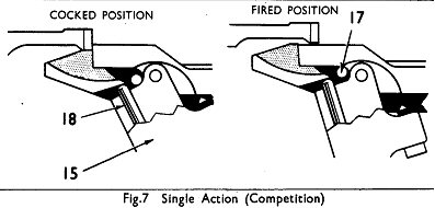
*Body ... ... ... ... ...... .........
******Trigger mechanism . ... ...... .........
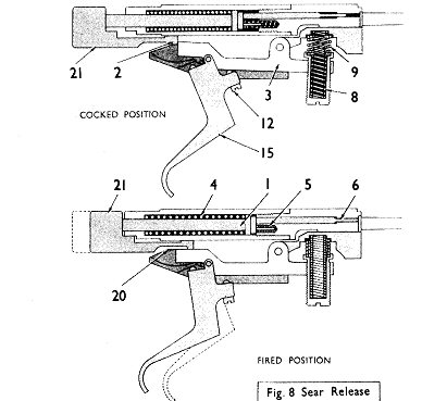
*Barrel .. ... ... ... ...... .........
*v*Safety devices ... ... ...... .........
*Stocking ... ... ... ...... .........
*********Cartridge platform and ejector.. .........
******Conversion to L2A1 ... ...... .........
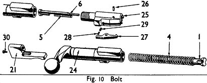
Section2 - Operation
**Loading ... ... ... ...... .........
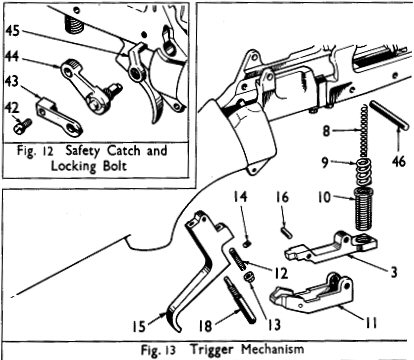
..
*****Trigger mechanism . ... ...... .........
*Sear .. ... ... ... ...... ......... .,
*******Withdrawal of firing pin ...... .........
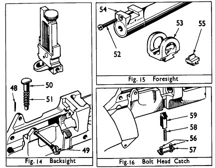
.,
*******Extraction and ejection ...... .........
..
Section3 - Servicing
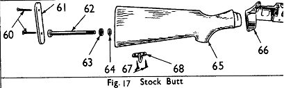
*Stripping ... ... ... ...... .........
**Assembling .. ... ... ...... .........
****Adjustments .. ... ... ...... .........
..
**Stocking up .. ... ... ...............
*Zeroing ... ... ... ...... ......... ..
****Altering length of butt ...... .........
*****Care and cleaning . ... ...... .........'..
******Additional technical points .... .........
**Section 4 - Examination
Bolt ... ... ... ... ...... ......... ..
*Body ... ... ... ... ...... ......... ..
***Trigger group ... ... ...... ......... ..
**Furniture ... ... ... ...... ......... ..
******Section 5 - Competition
Shooting
*********************************************************
L1ST OF ILLUSTRATIONS
*****Frontispiece ... ... ... Rifle No.8
Mk.I
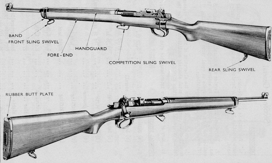
***Fig. 1 Service sights
2 Bolt
*******3 Safety devices
******************4
Cartridge platform and ejector
**********5 Trigger
mechanism
**************6 Double
action (service)
****************7 Single
action (competition)
******8 Sear release
************9 To remove
the bolt
**10 Bolt
****************11 Fore-end and handguard
*******************12 Safety catch and looking
bolt
*******13 Trigger group
****14 Backsight
****15 Foresight
**********16 Bolt head catch
******17 Stock butt
**18 Drift
********************19 Safety catch and locking
'bolt
*****************20 Cocking piece and striker
**************************************************
Section 1 - General Description
INTRODUCTION
**1. The rifle is a single-shot,
bolt operated weapon, similar in
characteristics to the No .4 Service Rifle upon which its design is
based.
2. Introduced into the Service as a training rifle, the No.8
was, however, designed as an accurate match shooting rifle. It
enables the Services to compete on equal terms with civilian
riflemen in small bore competitions.
**3. Provision is made for the
alteration of the trigger pressures
to suit either service or match shooting conditions, and for the
fitting of special competition sights.
**4. Many of the parts are interchangeable
with the No .4 Rifle.
5. - TECHNICAL DETAILS
Calibre...........................0.22 in.
Length of rifle, overall......(normal butt) ........41.05 in.
Length of barrel .......23.36 in.
Weight of rifle .........8 Ibs 14 ozs. (approx.)
Number of grooves ....................6
Pitch of rifling .........1 turn in 16 in.
Twist of Rifling .........Right hand
Head Space ... .........L.045 H.047
Striker protrusion......H.038 L.O34
Sight radius ... .........27.14 in.
Type of sights .........Rear aperture )
*********************************Fore blade***)) in Service condition
Sight range ... .........25 to 100
FORESIGHT.............................................BACKSIGHT
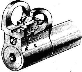
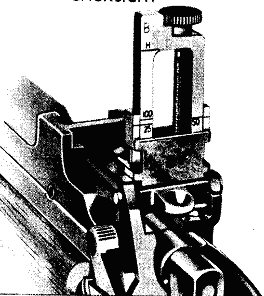
Fig. I Service Sights
FURNITURE AND EXTERNAL FITTINGS
6. Any of the approved hardwoods are used, i.e. Walnut, Beech, or Birch.
The front and rear handguards, stock fore-end and stock
butt being matched for colour.
7. The fore-end is slightly wider than that of the No .4 Rifle in
order to provide a better grip for the firer's forward hand.
8. Three sling swivels are provided, there being an additional
combination swivel and front trigger guard screw which can be used
for the fitting of a match shooting sling.
9. The stock butt is of the pistol grip type and is available in
three sizes; Long, Normal and Short.
SIGHTS
10. Service Sights (Fig.-l). - The fore and backsights issued with
the rifle are similar to those of the No .4 rifle, except that the
graduations are for ranges of 25, 50 and 100 yards, with an
additional harmonization (H) position provided for landscape target
practices.
11. Match Sights. - The standardized dovetail ensures quick
replacement of the service foresight with standard commercial
pattern match foresights.
Tapped holes in the body are provided, for the fitting of a trade
type match backsight.
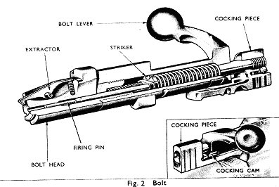
BOLT (Fig.2)
12. The No.8 differs from the No.4 in that cocking of
the action
is achieved by raising and lowering of the bolt lever only.
Although it is necessary to draw the bolt to the rear in order to
load, it is not necessary to do so merely to re-cock the rifle.
13. The rear end of the bolt houses a single cocking cam. When ,
in the withdrawn position the cooking piece is held to the rear
against the rear end of the bolt.
14. The striker is shorter than that of the No.4 rifle and is
designed to drive forward an independent firing pin which is housed
in the bolt-head and is off-set radially in order to strike the rim
of, and fire, the 0.22 in. cartridge.
BODY
15. The body is either a modified. No.4 rifle bolt body, or is a newly
manufactured body, similar to that of the No .4 rifle, with certain
internal machining operations eliminated.. The main differences
are:-
(a) The boltway is bored larger at the front end. to permit
entry of the rear end of the No.8 rifle barrel.
****(b) The lower part of the body is widened,
to accommodate the
cartridge platform.
(c) The rib on the No.4 rifle body, which retains the No.4
rifle bolt-head is machined off.
16. Tapped holes on the left side of the body are provided to
take a special match backsight.
TRIGGER MECHANISM
17. The trigger of the No.8 rifle can be adjusted to give either
the service double pressure, or a single match pressure. The
weight and length of the pressure can be adjusted in both cases.
**18. During release of the sear,
the cocking piece is supported by
the sear cradle. This eliminates drag between the sear and
cocking piece bents and ensures a clean and crisp let-off.
BARREL
**19. The barrel is shorter
and heavier than that of the No.4 rifle.
Its extra weight reduces to a minimum the vibrations set up in
firing and ensures a high degree of accuracy.
20. It has a plain bearing in rear of the breeching up thread;
this brings the chamber further to the rear and permits quick
loading in the lying position.
***21. The rifling is tapered,
being deepest at the breech end and
running out to almost bore diameter at the muzzle. The tapering
of the rifling gives an improved gas seal and also removes the
initial engraving from the bullet by the time it leaves the muzzle.
The purpose of this is to improve the standard of accuracy with
varying brands of ammunition.
*****22. The chamber has a plain taper
and the breech face is counter-
*******bored to take the rim of the cartridge;
it is further counterbored
to accommodate the rim of the bolt-head.
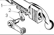
Fig.3 Safety Devices: (1) Bolt body; (2) Locking bolt;
(3) Safety catch
23. The applied, and. mechanical safety devices are similar
to those
of the No .4. rifle except for the following differences:-
(a) The safety catch engages in a hole in the bolt, instead
of in a cam slot.
(b) The rear safety recess on the cocking piece of the No.8
rifle is semi-circular and, unlike the No.4 rifle, does
not cause the cocking piece to be withdrawn when the
safety catch is applied, with the cocking piece in the
forward, position.
STOCKING
24. The bearings are the body seating, the reinforce, the middl
of the barrel and. the muzzle.
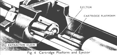
CARTRIDGE PLATFORM AMD EJECTOR (Fig.4)
25. There is no magazine. A cartridge platfonn is situated just
in rear of the chamber. The ejector is integral with the
cartridge platform.
CONVERSION TO L2A1
26. Some rifles will be converted, for use with R.A.C. miniature
range training by the removal of the foresight and. backsight and.
hand.guard.8 and. stocks. Such rifles will be known as "Rifle,
aiming, 0.22 in. L2A1".
Section 2 - Operation
LOADING:
27. As there is no magazine, the rifle must be loaded by hand for
each shot, as follows:-
(a) Push safety catch fully forward.
**************(b) Raise the bolt lever and
draw bolt fully to the rear.
******************(c) Place a cartridge in
the groove of the cartridge platform
then press the round forward with the thumb or finger
until the bullet has entered the chamber and resistance is felt.
*************(d) Grasp the knob of the lever,
thrust the bolt sharply
forward as far as it will go, then rotate the bolt lever
downwards, ensuring that it is fully down.
*****************(e) Repeat operation (b) to
(d) for each successive round.
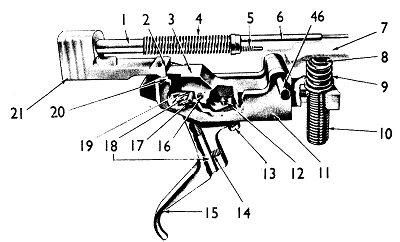
Fig. 5 Trigger mechanism
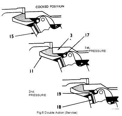
TRIGGER MECHANISM (Figs. 5, 6 and. 7)
28. Double Pressure - Service Condition (Figs. 5 and6) - When,
with the weapon cocked, the trigger (15) is pressed, the trigger
rotates initially about the cradle pin (17) as a fulcrum, levering
down the sear (3) in it's cradle (11), and rotating it about its
axis pin (46). This compresses the inner and outer sear springs
(8) and (9) and produces the first pressure. Continued pressure on
the trigger causes the protruding end of the pressure setting screw
(18) to contact the flat on the underside of the sear cradle (19),
to which the fulcrum point is then transferred and the leverage
altered. This produces the second pressure.
29. Single Pressure - Match Condition Figs. 6 and. 7).
- When it
is required, to adjust the trigger mechanism to a single pressure
for match conditions, the outer sear spring (9) is removed.. This
considerably reduces the trigger pressure. The pressure setting
screw (18) is then screwed in sufficiently for the trigger (15) to
rotate solely about the end of the screw and to avoid all initial
contact with the cradle pin (17).
30. Weight of Trigger Pressures. - The weights of both single and
double action pressures can be adjusted to fine limits by adjusting
the compression of the inner sear spring (8). This is
accomplished by screwing the sear spring cup (10) in or out.
SEAR
31. Sear Engagement (Fig.8). - The engagement of the sear (3) and
the bent of the cocking piece (2) is adjusted, before the weapon
leaves the factory, to a height of 0.03 in. by means of the trigger
setting screw (12). This setting normally should not require
adjustment.
32. Sear Release (Fig.8). - The pressure exerted by the compressed
sear springs (8 and. 9), transferred via the sear (3) and trigger
(15), combined with the direct pressure on the trigger, produces an
upwards thrust through the sear cradle pads (20) on to the base of
the cocking piece (21). This upwards thrust counterbalances the
downward drag of the bent of the sear on the bent of the cocking
piece (2) and prevents any axial movement of the bolt. When the
sear is released, the striker spring (4) carries forward the cocking
piece and striker (21 and 1) to drive the firing pin (6) forward on
to the rim of the cartridge, compressing the firing pin spring (5)
in so doing.
WITHDRAWAL OF THE FIRING PIN
35. When, after firing, the bolt lever is raised., the striker (1)
and. cocking piece (21) are withdrawn by the action of the stud on
the cocking piece in the cam slot of the bolt - similar to the
action of the No .4 rifle. The withdrawal of the striker allows
the firing pin spring (5) to re-assert itself and withdraw the
firing pin.
EXTRACTION AND EJECTION
54. When the bolt lever is raised, and the bolt withdrawn, the
empty case is removed from the chamber by the claw of the extractor
(Fig.4) pulling on the rim of the case. The empty case is held
between the claw of the extractor and the face of the bolt during
withdrawal of the bolt until the ejector (Fig.4) strikes the rim of
the case and ejects it from the rifle.
Section 3 - Servicing
STRIPPING
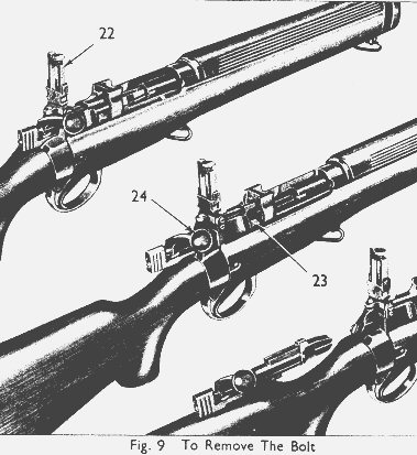
35. To Remove Bolt From Rifle (Fig.9). - Raise the backsight (22);
press down the bolt head catch (23); lift bolt lever (24) and pull
bolt back to its full extent. Release bolt head catch; raise
bolt head, and withdraw bolt from rifle.
36. To Strip Bolt (Fig.lO). - Unscrew the bolt head (25), and.
pull out the firing pin (6) and firing pin spring (5)- With a
suitable punch, drive out the extractor pin (26); remove extractor
(27), extractor plunger (28), and extractor spring (29). Remove
the striker screw (50) from the cooking piece (2l), and unscrew the
striker (1) with the "Tools Striker No.2" as used. with the No.4
rifle. Remove striker and striker spring (4) from the bolt (24).
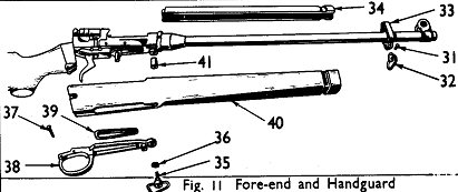
57. Fore-End and Handguard (Fig.n). - Remove the front swivel
screw (51) and remove the swivel (52) and band (55). Iiift off the
handguard (54), remove the front trigger guard screw (55), and
remove the spring washer (56). Remove rear trigger guard screw
(57); remove trigger guard (58) and trigger guard filler (59).
Remove the fore-end (40), and collar (41)o
38. Safety Catch and Locking Bolt (Fig.12). - Remove the locking
bolt screw (42); looking bolt spring (43) and. remove the locking
bolt (44) and safety catch (45) from their housing. Unscrew safety
catch from locking bolt.
39. Trigger Mechanism (Fig. 13). - Drive out the rear cartridge
platform pin (46) and. pull trigger assembly downward out of the body.
Remove the inner and outer sear springs (8 and 9) and slide the sear
cradle (11) down over the trigger (15). Take out the trigger pin
(16) and separate the trigger from the sear (3). Unscrew the sear
spring cup (10) from the sear.
40. The sear bolt and. its spring, which are housed in the sear to
check rotation of the sear spring cup, are burred in and cannot be
removed. To strip the trigger, remove the pull-off locking screw
(14) and pull-off setting screw (18); remove the trigger setting
screw nut (13) and trigger setting screw (12).
41. Cartridge Platform. - The cartridge platform should not be
removed., since the hole for the front pin is drilled on assembly,
making the platform a special fit to the body. If through wear or
breakage it is required to replace the ejector this will be done as
a factory repair.
42. Backsight (Fig.14). - Tap out the backsight axis pin
retaining pin (48) and drive out the backsight axis pin (49).
This releases the backsight assembly. Lift the backsight plunger
(50) and its spring (51) from their housing.
43. Foresight (Fig.15). - Unscrew the clamping screw (52) and
slide the foresight protector (53) out of its dovetail in the
barrel band (54). Tap the foresight (55) out of the dovetail in
the foresight protector.
44. The barrel band is pinned and sweated on to a reduced
diameter at the end of the barrel and must not be removed.
45. Bolt Head Catch (Fig.16). - Undo the two screws (56)
holding
the breech bolt head catch retaining plate (57); lift the spring
(58) and breech bolt head catch (59) from their seating.
46. Stock Butt (Fig.17). - Remove the two stock butt plate screws
(60) and lift off the butt plate (61). Remove the stock bolt (62)
and take the stock bolt spring washer (63) and washer (64) out of
the stock butt (65). Pull the stock butt from the body socket (66).
Remove rear swivel screws (67) and rear swivel (68).
47. The rifle should be assembled in the reverse sequence of the
order of stripping. The only difficulties likely to be experienced
are in the securing of the trigger group to the body; screwing the
cocking piece onto the striker, and in assembling the safety catch
and locking bolt. Instructions on these points are given below.
ASSEMBLING
48. Trigger Group. - To enable the rear cartridge platform pin to
be driven in to secure the trigger group, the holes in the rifle
body, cartridge platform, sear cradle, and sear must all be exactly
aligned at one and the same time. This is extremely difficult
without the aid of a guide drift, and damage to components will
result if any attempt is made to drive the pin through the holes
when they are aligned by any less precise method.
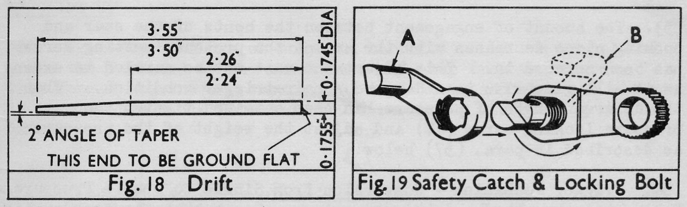
49. The drift used should be in accordance with the dimensions
shown in Fig.18. The holes in the trigger group should be aligned
as nearly as possible by eye and the tapered end of the guide drift
passed through them; the guide drift should be pushed or gently
tapped through until the ground end is flush with the body of the
rifle. The end of the rear cartridge platform pin should then be
placed on the end of the guide drift, and the guide drift driven
through the rifle body by the pin. The ends of the pin and the
guide drift should be kept in close contact with each other during
the time the pin is being driven through.
50. Safety Catch and Locking Bolt (Fig.19). - It is important
that the threads should be picked up correctly when the locking
bolt is screwed on to the safety catch. To assist in correct
assembly, fig.19 shows them (A) positioned as they should be before
engagement of thread, and (B) when screwed fully home.
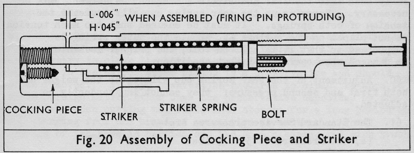
51. Cocking Piece (Fig.20). - To ensure correct functioning it is
essential that the cocking piece should correctly be assembled to
the striker. The two components should be assembled as shown in
the illustration.
ADJUSTMENTS
52. Trigger Mechanism - Conversion from Double to Single Pressure.
Remove the trigger guard and trigger group. Remove the outer seal
spring (9) and re-assemble with the inner spring only (8). Loosen
the pressure locking screw (14). Screw in the pressure setting
screw (18) a half-turn at a time until a single pressure is
obtained. When the weapon is cocked the pressure setting screw
should now bear on the underside of the sear cradle web, not on the
sear cradle pin which is not used as a fulcrum in single pressure
match condition.
53. The amount of engagement between the bents of the
sear and.
cocking piece decreases with the amount the pressure setting screw
has been screwed in. This adjustment must not be carried to excess
as it will give rise to a dangerous hair-trigger condition. When
the desired length of pressure has been obtained, tighten the
pressure locking screw (14) and adjust the weight of the pressure
as described in para. (57) below.
54. Trigger Mechanism - Conversion from Single to Double Pressure.
Remove trigger guard and trigger group. Screw home the sear spring
cup, replace the outer sear spring (9), and re-assemble the trigger
mechanism. Loosen the pressure looking screw (14), and screw out
the pressure setting screw (18) a half-turn at a time until a
double pressure is obtained.
55. When the weapon is cocked the flat on the top of the trigger
should now bear against the cradle pin (17). The length of the
pressures can be adjusted by screwing the setting screw in or out.
56. Tighten the pressure locking screw and adjust the weight as
described in para. 57 below.
57. Weight of Trigger Pressure. - For single pressure action,
with the inner sear spring only in position, the trigger pressure
weight can be adjusted by screwing the sear spring cup (10) in or
out. This alters the tension of the sear spring. One quarter
turn (one click) of the sear spring cup makes a difference of 2.5
ounces to the pressure weight.
58. The minimum match condition weight of 3 lbs. can be adjusted
within close limits.
59. For double pressure trigger action, both sear springs must be
in position. The sear spring cup initially should be screwed
fully down into the sear and little subsequent adjustment will be
necessary. Screwing up the sear spring cup will increase the
tension of both springs. It must be ensured that too much tension
is not placed on the springs as, should the outer spring be
compressed so that it is coil on coil, the trigger mechanism will
be damaged when operated in that condition.
60. Adjustment of the sear spring cup will alter the weight of
both first and second pressure; they cannot independently be
adjusted.
61. The Standard Service pressures are:-
(a) 1st Pressure 3 to 4 lbs.
(b) 2nd Pressure 5 to 6.5 lbs.
STOCKING-UP
62. Test for bearings on body and barrel. Hold the barrel and
press the fore-end of the stock fore-end away from the barrel.
This should require a pressure of 3 to 5 Ibs., and when the pressure
is removed the stock fore-end should return to its seating on the barrel.
ZEROING
63. The No.8 rifle is zeroed, by alterations to the size and
position of the foresight, in a manner similar to that used with the
No.4 rifle. The foresights used are the same as those issued for
the No.4 rifle. They are 8 in number ranging from -0.03 in. to
+0.075 in. in steps of 0.015 in. One change of foresight (of
0.015 in.) will make a vertical alteration of MPI of approximately
1/2 in. at 25 yards.
64. The rifle should be zeroed so that the MPI is at the point of
aim with the backsight set for the range used.
65. The foresight should be set laterally with the Tool, Foresight
cramps No.3.
ALTERING LENGTH OF BUTT
66. Three different lengths of butt, long, medium and short are
provided. The variation is the same as for the No.4 rifle - 1/2
inch each side of a medium length of approximately 13 inches.
67. The method of stripping the butt for exchange of size is
shown in Section 1, para.46.
CARE AND CLEANING
68. The exterior and working parts should be cleaned in the same
manner as the No.4 rifle.
69. The 0.22 in. ammunition issued to the Services, and most makes
of commercial ammunition, are non-rusting, therefore it normally is
not necessary to clean the bore after firing. The deposit
remaining in the barrel after firing is a preservative and should
not be removed. It may, however, be required to clean the bore to
remove foreign matter other than the preservative deposited by the
ammunition, when putting the rifle into storage for a long period or
when changing from one brand of ammunition to another. When
cleaning of the bore is carried out the No.6 cleaning rod with Brush
and Cleaner should be used. Regulation flannelette, size 2
x
1 .1/8 in., and oil should be used. It is not necessary to use
boiling water.
ADDITIONAL TECHNICAL POINTS
70. Mainspring. - The bolt should be removed from the rifle in
order to check the tension of the mainspring. The tension of of
the spring is ascertained by weighing the effort required to move
the
cocking piece in both the fired and cocked positions.
Mean weight in fired position = 13 lbs.
Mean weight in cocked position = 15.25 lbs.
If in the fired position the weight falls below 12 lbs. the
mainspring should be replaced.
71. Extractor. - The approximate mean weight exerted by the
extractor spring is 3 lbs. This should be tested by exerting
pressure on the tail of the extractor, as it is difficult to weigh
by lifting the claw and may cause damage to the extractor.
72. Sear and sear cradle. - The setting of sear and
sear cradle
should be checked from the boltway, on the assembled rifle, to
have a clearance of 0.03 in.
73. Barrel. - Gauge bore with cylindrical acceptance plugs
L.0.216 inch must run. The barrel should be free of any lateral
influence by the fore-end.
Section 4 - Examination
BOLT
74. Examine for wear, corrosion, and burrs. Remove all burrs by
stoning, taking care to avoid removing any metal (other than the
burr) from the rear faces of the locking lugs and the cartridge face.
75. Examine the bolt head for corrosion, wear, and burrs.
Remove any burrs by stoning. Ensure that the extractor, extractor
plunger, and extractor spring work freely in their recesses.
76. Examine the extractor and firing pin for wear, damage,
corrosion and distortion. Examine the extractor spring, firing pin
spring, and striker spring for corrosion, fractures and collapsed coils.
77. Examine the cocking piece and striker for burrs, distortion
and damaged threads.
BODY
78. Examine for corrosion, burrs, distortion and fractures.
Ascertain that the cartridge platform pins are a tight fit.
TRIGGER GROUP
79. Examine the components for burrs, corrosion, distortion and
damaged threads.
80. If the top corner of the sear bent is rounded, a little metal
may be stoned from the upper surface to correct it. Care must be
taken to avoid altering the angle between the top and rear faces of
the sear, and stoning must not be resorted to unless it is
considered that the fault has developed to an extent which will
cause a "woolly" release of the cocking piece.
FURNITURE
81. Examine the furniture for cracks or other damage and ensure
that the stock butt is a firm fit in the butt socket. Examine the
stock fore-end and handguard for warping.
Section 5 -Competition Shooting
82. The sights issued with the No.8 rifle are replicas of those
on the full-bore service rifle and are designed primarily for use
under service firing conditions. For competition shooting under
Match conditions, more accurate sights, capable of fine adjustment
will be required. These match sights will not be issued, but will
be provided, if required, by individuals, or rifle clubs in the same
way as special sights are used for S.R.b shooting at Bisley and elsewhere.
83. To assist in the fitting of Match backsights to the No.8 rifle,
three holes have been provided on the left side of the body. The
three holes are tapped for 4 B.A. and 3 B.A. threads and are
normally closed with a cheese-headed screw to prevent the ingress
of dirt. The screws are removed before fitting a Match backsight.
84. It may be necessary to remove the Service backsight before
certain types of Match sights can be fitted to the rifle.
85. The Service foresight is designed for easy removal when
it
required to fit a Match foresight of the tunnel variety. The
dovetail on the block is of standard size and will take the normal
commercial pattern of foresights. When fitting certain types of
commercial foresights it may be necessary to make a small groove
in the underside of the sight in order to accommodate the clamping
screw. It is emphasized that if any modification is necessary it
must be made to the purchased sight - not to the foresight block
of the rifle.
86. Details of the various trade pattern match sights suitable
for fitting to the No.8 rifle, together with advice and information
on small bore matters generally, may be obtained from the Army Rifle
Association, or from the National Small Bore Rifle Association.
Back to: Rifle No.8 page
Return to: TOP of PAGE
See this website's Raison d'être