The following article has been contributed by a collecting enthusiast and colleague from Australia. We thank Nicholas O'Brien for this fascinating and little-known information, including the photographs, about a most unusual product of the Birmingham Small Arms Co.
The background story of this 1927 BSA sight may possibly relate to the U.K. dominance of the Parker family in the manufacture of target shooting equipment from 1909. Many other British makers suffered commercially under the success of A.J. and A.G. Parker and, latterly, Parker-Hale; Fraser, Mansfield, Gibbs, Westley Richards, London Small Arms, and even W.W. Greener, just to name a few, faded from the scene. Even the BSA service rifle aperture sights were much less seen, perhaps anyway as a result of their association with Parker designs; although BSA continued to be very active, producing a continuous stream of military rifle patents and sight designs for their various .22 target rifles. One exception to those military items is their 1927 patent application no.24,956 for an aperture target rear sight. This 1927 model superficially looked to be a competitor to the hugely successful Parker-Hale model PH5A, which sold in thousands over more than 25 years.
No source has been identified to suggest this 1927 patented BSA sight was ever made commercially in any significant quantity. The particular design was unknown even to a few specialist collectors in the UK who hold similarly rare pre-war BSA and Parker/Hale sights in their collections.
 ....
.... .....
..... 
The patent document is particularly interesting, as it describes a seldom discussed aspect of the Lee Enfield action, in that that the usual locations on the action body, used for mounting target sights, are not gauged during manufacture. The forgings were, in this respect, finished to dimensions that were not critical from an inspection point of view.
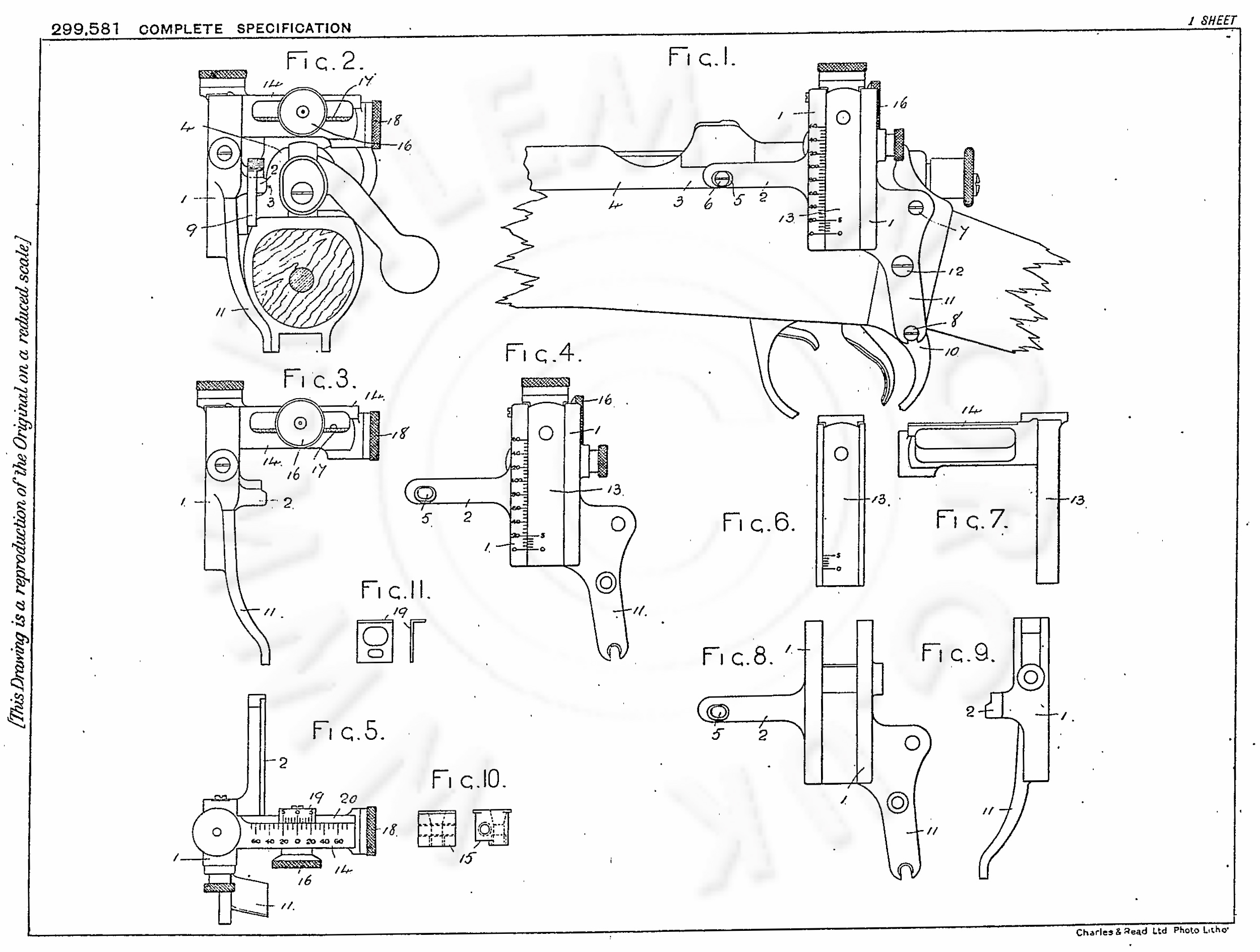
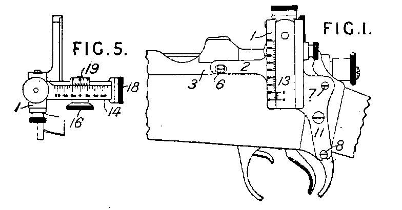
The front page of the patent document showed a basic drawing and précised version of the text of the main pages.
Birmingham Small Arms Co., Ltd., and Norman, G.
Original application date: Sept. 22, 1927.
Sights.- Relates to back sights the frame (1) of which is provided with a rear limb (11) adapted to be secured against the side of a rifle, and consists in providing the frame with a front arm (2) arranged to lie along a gauged part (3) of the side of the rifle and to be secured thereto by a screw (6), e safety lever and trigger guard. The frame (1) carries a vertically adjustable pillar (13) provided with an horizontal arm (14) along which is adjusted by means of a screw a hollow block carrying an aperture sight (16) and a vernier scale (19) moving along a scale on the top of the arm (14). The screw is rotated by a knob (18) provided with a clicking indicator.thus ensuring the vertical position of the frame (1). The screw (6) serves also for the ejector; and the rear limb (11) is secured by the attachment screws (7, 8) of the safety lever and trigger guard. The frame (1) carries a vertically adjustable pillar (13) provided with an horizontal arm (14) along which is adjusted by means of a screw a hollow block carrying an aperture sight (16) and a vernier scale (19) moving along a scale on the top of the arm (14). The screw is rotated by a knob (18) provided with a clicking indicator.
The complete text of the patent document is shown as a searchable PDF further down this page, along with the full drawing.
This meant that those surfaces would not necessarily locate the aperture sight, nor its mounting plate, parallel with, or perpendicular to, the bore; and it is quite common to see the sights of the day (like the PH5A, which has no in-built feature to set it square) needing filing or packing to achieve perfect alignment. This problem is present with those mounting plates of the day which use the trigger guard screw, like the early Parker plates for the Lee-Enfield; and including the early Australian plates such as the “MA” marked Lithgow model (and the derivative Argyle plate).
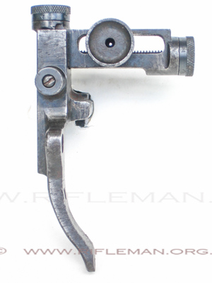
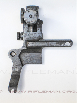
BSA’s 1927 patent overcame the surface location problem by using three attachment points, one more than the PH5A. The third fixing was the ejector screw. Incorporating three fixing screws must have made this a more expensive design to manufacture compared with the PH5A.
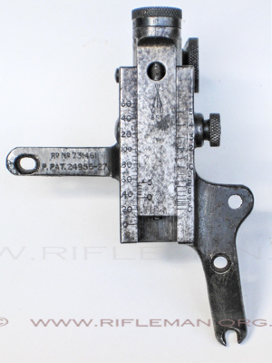
The sight is marked “P. Pat. 24,956”, and also “R’D 731461”(Registered Design). The text of the patent’s provisional specification application preceded that of the wording in the final acceptance as Patent No. 299,581 on 1st. November 1928. The actual sight example illustrated in this article does not carry the usual drawing part match marking number references used; (The match mark numbers are used in mass production so that each finished sight, having the correct working fit, has the critical parts match numbered. This prevents incorrect parts being assembled later in production). Most British sight designs showed a two, (or three), digit number that related to production batches of up to 100 (or 1000) items. That may perhaps suggest that this particular 1927 BSA sight is a hand-fitted unit rather than an example of one from a large production batch.
The side of the wind-arm displays the usual BSA piled arms mark. The thick wind-arm arrangement is unusual in that the eyepiece is integrated within it. The sight itself is very neat, and the flush-fit adjusting knobs are a detail which would not look out of place on a sight made today. These flush-fit knobs have the axial play adjusted by using a screwdriver in the slot on the opposite end of the adjusting screw; similar to the early Parker-Hale model 6E design for the Lee-Enfield action. Each knob has been pinned to its shaft, presumably after factory adjustment.
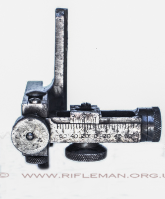
The sight uses the usual British 1/100th inch vernier scale. By 1927 this did not give true minute adjustment for the shorter sight radius of the SMLE (Rifle, Short, Magazine Lee-Enfield). It is doubtful that anyone would have contemplated fixing this sight, as calibrated, to a 'Long' Lee-Enfield rifle, (where this vernier would give true minutes on the issue 30.2” barrel length) as, by the mid 1930s, the 'Long' charger-loading Lee-Enfield (C.L.L.E.) was approaching supercession in British competitive shooting, although high quality 'regulated' volunteer models were perhaps still a practical proposition at long-range.
The sight's elevation dovetail has a lock-screw which needs to be loosened each time an elevation change is made. The locking screw is spring-loaded, and allows the wind-arm to slide vertically from the rifle for safe storage; much like the PH5A. An additional novel feature of the wind-arm design, with the eyepiece being used to lock the wind-arm carriage, is much like the adjustment of the BSA No.8 sight for the Martini actions. These separate locking functions would make a combined elevation/wind adjustment slower than any comparable sight, but they also guarantee complete rigidity once locked down.
The wind vernier scale is graduated to 60 minutes, though only about 35 minutes adjustment can be made before the wind carriage binds up either side. Each “click” of elevation or windage is ½ minute. While the wind vernier scale can be set to zero, the elevation scale cannot. It is also graduated up to 60 minutes (though not all of this will be available vide the lack of a zero feature) and the range scale is graduated from 0-1500 yards. The range scale is again anomalous, since the Mk.VII cartridge requires a 124 minute rise from 300 yards (or 132 minutes from zero range) according to the Vickers Mk.VII slide rule. The patent drawing shows only an elevation scale in minutes.
The sight is all steel with the usual deep blued finish. This surviving example shows spots of surface corrosion, although the sight still functions well.
The comments above about the ungauged receiver locations are recognised in the design. The hole for the ejector screw (part no.5) is slotted horizontally to allow a small amount of adjustment for the expected variations. Slotted mount points are an uncommon feature in target aperture sight designs. Some designs, including this one, have an open-ended fork for the trigger guard screw, which gives a very small vertical tolerance. This 1927 BSA design has a small spigot (to be seen on the patent drawing) at the trigger-guard screw location, which tightly fixes that screw location. All three mount screws needed to be round-headed, with a head diameter of just under ¼”. Fitting this sight to the SMLE would have presented a drawback compared with nearly all others – the third fixing point requiring a 0.145” longer ejector screw in the special 0.1656” x 37 tpi (threads-per-inch) Enfield thread. It is possible that this could be made from a back-sight cap-screw by reducing it’s 0.299” head diameter.
BSA REAR-SIGHT PROVISIONAL SPECIFICATION of 1927 - ACCEPTED 1st. NOVEMBER 1928