The Short Magazine Lee-Enfield Rifle ( S.M.L.E.)
Please be aware that some specialist imagery may take time to load.
This site is for dedicated researchers and is best viewed on desk or laptop.
See also the SMLE portable sub-target device or the .22 Pattern '14 conversion of the No.1 Mk.1
For the uninitiated, it should be mentioned that the terminology officially used for this rifle is rather ambiguous. It could easily be understood that the rifle has been designed with a 'short magazine' when, in fact, it is the rifle that is short rather than the magazine.
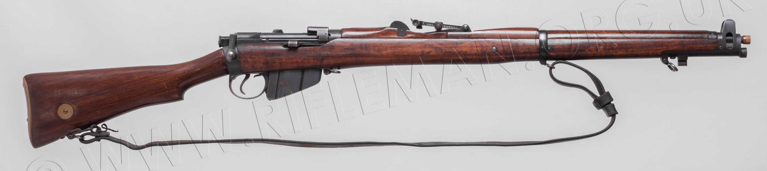
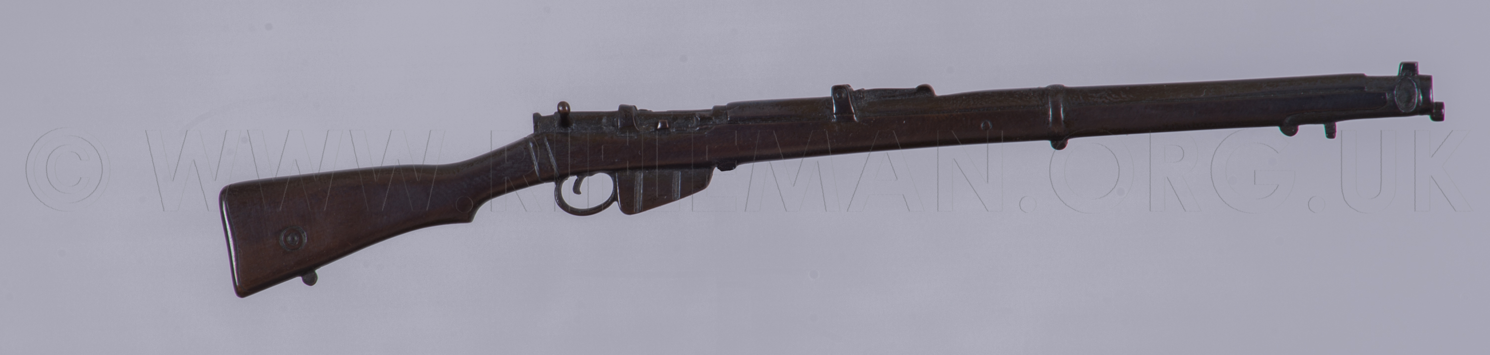
Below: the original rifle, latterly known as the "No.1" Mark I
The terminology of the day used by the military was " Rifle, Short, Magazine, Lee-Enfield "; the punctuation applied illustrating that the rifle, as shown above, was a shortened version of the original Magazine-fed Lee-Enfield (M.L.E) which preceded it, an example of which is shown below in the form of a .22RF conversion fitted with the rare Hiscock-Parker magazine
This former rifle is now more commonly known, in its various marks, as the 'Long' Lee-Enfield, and the latter shortened successor, first introduced in 1903, as the 'Short Magazine Lee-Enfield' or "S.M.L.E.". The initials have, unsurprisingly, been modified both in use in military and civilian circles to the colloquial term "Smellie", by which this famous British service rifle is fondly (or otherwise) described, particularly by those who had been required to carry it in one or other of two World Wars or the many arenas of conflict and policing World-wide between those wars. Indeed, the later marks of this rifle are still to be found in occasional use in some parts of the World, and have been the mainstay of some Asian countries, notably in India, until superseded by the No.4 rifle when Britain introduced the FN SLR (Self Loading Rifle)
The most significant detail of the conception and introduction of the "New Short Rifle" is to be found in the 1904 publication by Her Majesty's Stationery Office of the "Text Book of Small Arms". Covering most of the important rifles, carbines, pistols and bayonets of the time, it afforded a brief history of the progress of British service arms from early times through the flintlock (Baker), percussion (Minié) and breech-loading rifles, with greater detail of the Martini-Henry/Enfield and Lee-Metford/Enfield "Long" rifles and, from page 29, a section on the Small Arms Committee formed to discuss the requirement for a shorter model and trials of same.
This section is replicated below, and followed by the later entry, from page 72 to 78, that covers the steps leading to the introduction of the new rifle. It is interesting to note a few differences in the 1,000 trials rifles from the finally adopted rifle, including the lack of a butt trap to hold an oil bottle and bore-cleaning pull-through. The butt-plate was a flat steel item. Certain sighting differences will be noted too, 500 of the trials models having a tangent rear-sight that was the precursor to the eventually issued type.
The drawings are included, and are zoomable for detail.
In January, 1900, a Committee was appointed to report upon matters connected with small arms. In 1901 they recommended that 1,000 experimental short L.-E. rifles should be issued to the troops for trial. These rifles were issued in June, 1902; they were 5 inches shorter than the L.-E. rifle, and were suitable for use by both Cavalry and Infantry; thus the accuracy of the fire of the former, when employed dismounted, should he equal to that of the latter. The principle of multiple loading was adopted; and the rifles were fitted with guides to hold chargers, from which five cartridges could be swept into the magazine with the thumb; the empty charger is then thrown away. The magazine still held 10 cartridges as before, so that if necessary 10 cartridges could be inserted, or if only one charger full had been inserted, the magazine could be replenished by another charger full of cartridges before it was completely emptied.
Another feature was the more delicate sighting. The fore- sight consisted of a bead, capable of lateral adjustment, protected by a hood, so that the small variations in the shooting of different rifles could easily be corrected (see Fig. 2).
Five hundred of the rifles were provided with a backsight in which the leaf is pivoted in front; a single V being cut in the cap at the rear end (see Fig. 13, Chapter 5).
The other five hundred rifles were provided with a leaf somewhat similar to the ordinary L.-E. leaf. The axis pin was replaced by a screw, by means of which the entire leaf could be traversed to one side for wind allowance (see Fig 14 Chapter 5).
The rifles retained the aperture and dial sights, a long hand guard, reaching from the body to the nose-cap was added and the bolt cover omitted. The pull-through and oil bottle were not carried in the butt, therefore there was no trap in the butt plate.
Since writing the above, the reports of the trials of the rifles by the troops have been received, and a pattern has been adopted and sealed. A description of it will be found in Chapter 4, page 72.
The above gives an outline of the introduction of magazine arms, by this and other countries.
Their advantages, when combined with a small bore, and smokeless powder, in comparison with large bore single breech loaders, are as follows:—
Rapidity of fire.
Flatness of trajectory.
Increased range and penetration.
Smokelessness.
Cartridges lighter, therefore more can be carried.
Less recoil.
Rifle handier and more accurate.
_________________
HERE FOLLOWS
THE 1904 SECTION FROM CHAPTER 4
DESCRIBING THE NEW SHORT RIFLE
_________________
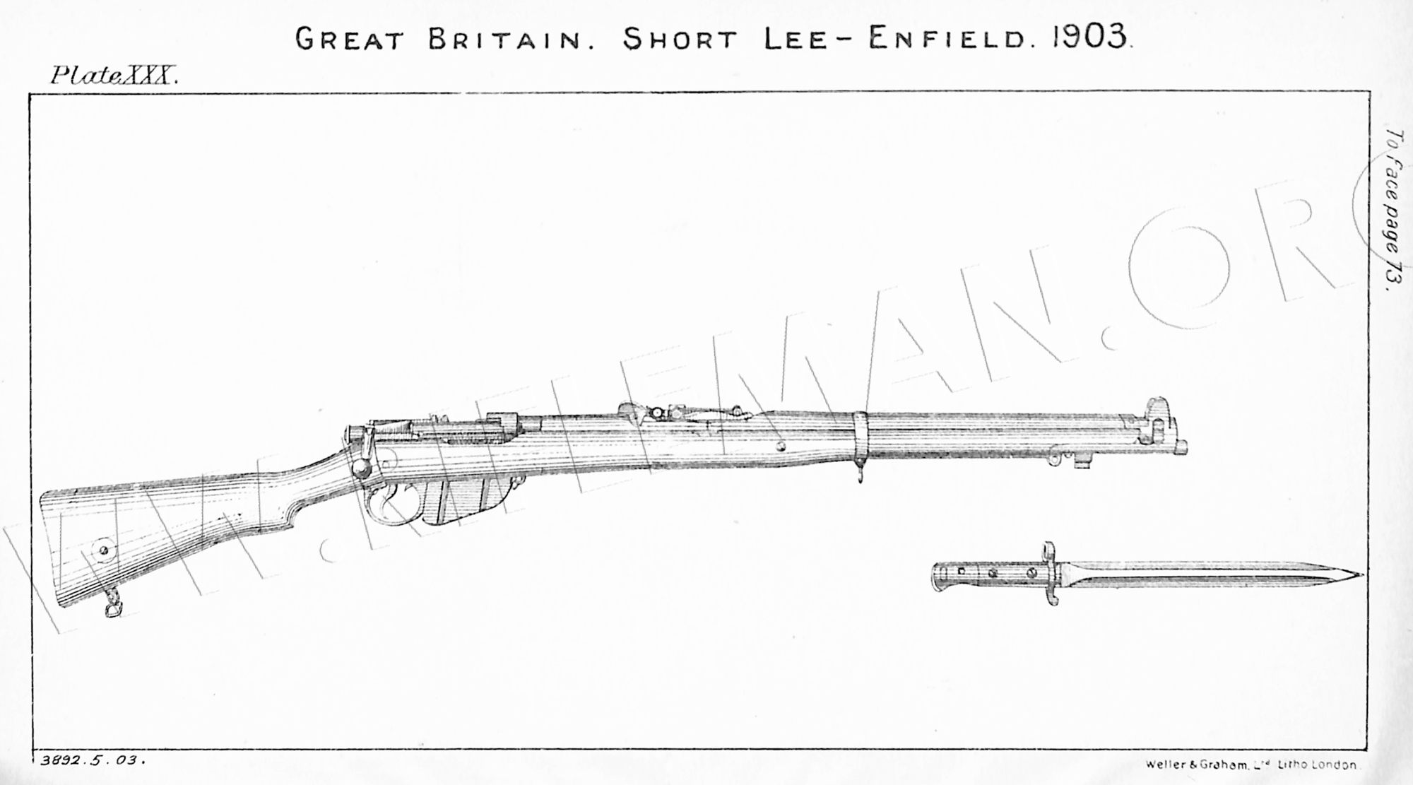
Short Lee-Enfield. 7.7 mm. .303-inch pattern, 1903.
The steps leading to the introduction of this rifle are detailed in Chapter II.
[Ed: this is the section you have just read].
Hover over or Click image to bring up hi-res file and magnifier
The barrel, which screws into the body, is rather thinner, and is 5 inches shorter than that of the Lee-Enfield rifle. It is strongly reinforced at the breech end, which is provided with a "Knox form," as in the Lee-Enfield rifle. The grooves of this rifle are of the same shape as the Enfield rifling, but the bore increases in diameter and the rifling muzzle. This gives the rifle the same velocity as the Lee- Enfield rifle.
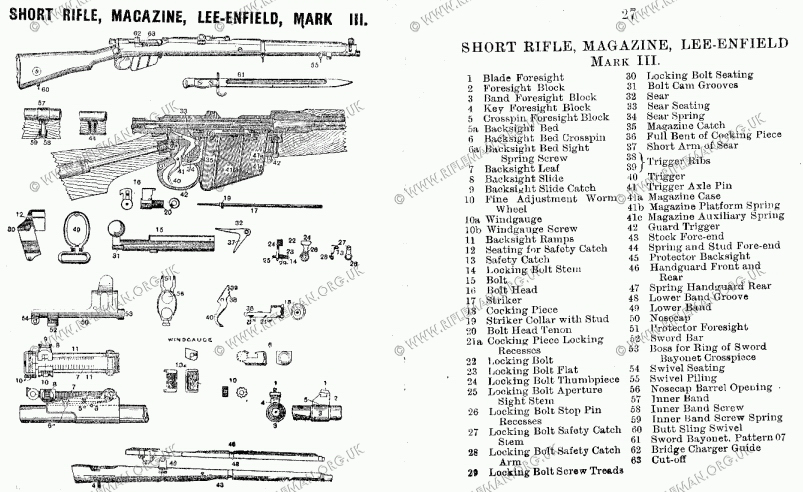
The foresight consists of a barleycorn (1) dovetailed into the foresight block (2) at right angles to the axis of the barrel so that it is capable of lateral adjustment. The foresight block is formed with a band (3) which fits the barrel; it is kept in position by a key (4) and crosspin (5); it is set .015 left to counteract the lateral vibrations of the barrel set up on firing. The barleycorn may perhaps be replaced later on by a bead foresight. The backsight bed fits on to the top of the barrel, to which it is attached by a vertical screw at each end and by a crosspin (6) in the middle. The leaf (7) is grooved out underneath for lightness, and is pivoted at its front end; at the rear end is a fine adjustment slide (8), which is dove-tailed to the leaf, and is capable of being moved up and down vertically by means of the screw (9); this constitutes a method of obtaining a fine adjustment for target shooting for intermediate elevations between the 50-yard graduations obtain able by means of the slide. On the left edge of the fine adjustment slide and leaf is a scale, the divisions on which represent an alteration of elevation of 6 inches on the target per 100-yards. The screw (9) works in the projection (8a) on the fine-adjustment slide, the motion of the latter is limited by the stop screw (85) which works in a groove on the edge of the projection (8a). The V for aiming with, is cut in the wind-gauge slide (8c). A projection on the hack of this slide works in a slot in the rear face of the fine adjustment slide; this projection has a threaded hole in it, in which the stem of the screw (8d) works. Between the head of tlic screw (8d) and the slide (8) is the dished spring washer (8e) the friction of which prevents a worn screw from turning too easily. A keeper plate is dovetailed into the end of the slide (8) next to the washer (8c); it fits into a groove in the stem of the screw (8d) and keeps it in place. To strip the fine adjustment and windgauge slides the keeper screw (8b) must first he removed. On the rear face of the windgauge, and fine adjustment slides, is a scale giving an allowance for each division of 0 inches on the target per 100 yards. The slide (10) fits on the stem of the leaf and bears on the ramps (15) at each side of the bed; it has an opening on top through which the figures on the leaf may be read. Into each side of the slide a catch (11) is inserted. A bone stud (12) fits into the outer end of the catch, and a tooth (13) is formed at the inner. Short spiral springs bear against the heads of the catches at (11) and keep them pressed outwards. The top surface of the leaf is graduated by equidistant lines for elevations from 200 to 2,000 yards, and the sides of the leaf are provided with notches for the teeth (13) of the catches to fall into for every rise of 50 yards in elevation between the above limits. The catches engage in the notches alternately, the right catch engaging at each 100-yard graduation. To adjust the slide, press both bone studs inwards, between the finger and thumb, this releases the teeth (13), then move the slide until the line across its top surface is at the required elevation on the leaf, and release the pressure on the studs. The studs are of bone to prevent the finger and thumb being burnt when adjusting the sight which gets hot during rapid and sustained fire. Between the ramps is a flat backsight spring which is screwed at its rear end to the bed, its front end presses upwards against the leaf in front of the joint, so that the slide (10) is always pressed down on to the ramps (15).
The long range sights are identical with those described for the Lee-Enfield rifle.
The body is similar to that of the Lec-Enfield rifle with the body,
following exceptions:—
The left side of the body is raised to act as a charger guide, and a small groove (16) is cut to receive one of the stops on the charger (see Plate LXII). In front of the charger guide a deep recess (17) is cut in the left side of the body to enable the thumb of the right band to sweep the cartridges out of the charger. The resistance shoulder is formed with a small projection for the rear end of the charger guide (22), on the bolt-bead, to bear against. No cut-off is provided, but the cut-off slot is left in case it be found advisable hereafter to re-introduce one. A hole (19) is bored through the left side of the body near the rear for the safety catch (44), and below it another hole for the stem of the locking bolt (38) leads into the cocking piece groove.
The bolt (20) is similar to that of the Lee-Enfield rifle with the following exceptions :—
The prolongation in rear of the bolt handle is cut off, as it is no longer required, since there is no safety catch attached to the cocking piece (30). As there is no bolt cover, the projections and groove for the latter are omitted.
The bolt-head (21) is similar to that of the Lee-Enfield rifle, but it is fitted with a charger guide (22) which works upon the top surface of the projection for the extractor.
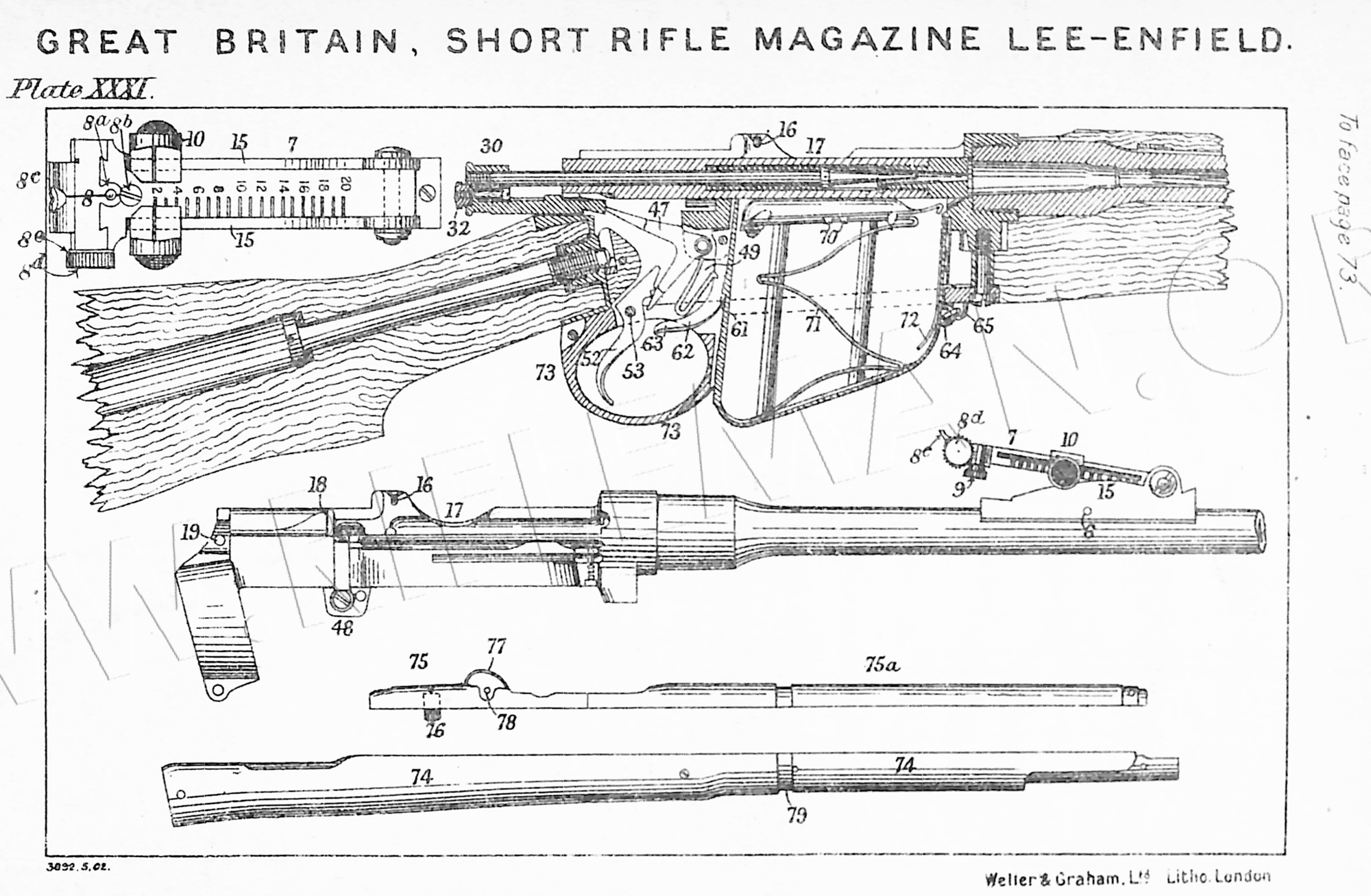
The charger guide is connected to the bolt-head by means of an undercut, rib (23) on the latter, working in an undercut, groove (24) in the former. A keeper screw fitting in the recess (25) in the end of the charger guide prevents the latter from coming off the bolt-head. A small groove (26) is provided for one of the stops on the charger to fit into. When the bolt is being closed, the front end of the charger guide strikes against the body, and slides back until its front end is flush with the projection for the extractor on the bolt-head. On drawing back the bolt, the rear end of the charger guide strikes against the projection (18) on the resistance shoulder, and is pushed forward as shown at A, into such a position that the groove (26), on the bolt-head charger guide, is opposite the groove (16) in the charger guide on the body. The charger can then be inserted, and is firmly held while the cartridges are being pressed into the magazine.
The mainspring consists of 32 coils of 0.049 wire, set to a length of 3½ inches.
The striker (27) passes through the bolt; its rear end screws into the cocking piece (30). It has a collar near its front end for the mainspring to bear against. In front of this collar is a small projection (28) which fits into the recess (29) in the rear end of the bolt-head tenon.
The cocking piece (30) is similar to that of the Lee-Enfield rifle with the following exceptions :—
The projections for the safety catch is omitted, and also the hollow sleeve which fitted over the rear end of the Lee-Enfield bolt. In place of a keeper screw a recess (31) is formed for a keeper nut (32), which, when in position, has a shank (33) screwed into it. A spiral spring fits on this shank which works in a longitudinal hole drilled in the cocking piece. This spring draws the nut forward into its seating (31), where it locks into the recess (32a) on the end of the striker and prevents the latter from turning. The nut also has a small pin (34) driven into it which fits in the recess (35). On drawing the nut to the rear and giving it a quarter turn, the pin (34) rests on the rear face of the cocking piece, and the striker can then be unscrewed and the bolt stripped. This can be done by unscrewing the bolt-head, for the recess (29) in the latter engages the projection (28) on the striker and unscrews it. The two recesses (36) on the left side of the cocking piece are for the locking bolt to engage in.
The locking bolt (37) is provided with a stem (38) which, fits into a hole in the left of the body leading into the groove for the cocking piece. The end of the stem is cut away at (39), so that when the roughened thumb piece (40) is in the forward position, the cocking piece passes over the end of the stem, where it is cut away, but when the thumb piece is drawn to the rear, the solid portion of the end of the stem engages in the back or front recess (36) of the cocking piece, according to whether the latter is in the fired or cocked position, and locks it securely. When the end of the stem (38) engages in the recess (36) it draws the cocking piece back slightly.
The aperture sight fits on to the stem (41), and the head of the aperture sight spring, which is similar to that of the Lee-Enfield rifle, keeps them all in position. The small hole (42), on the inner face of the locking bolt, has two stop-pins provided for it, on the exterior of the body, on to one of which it drops when the locking bolt is in the backward or forward position.
The locking bolt safety catch (43) is formed with a stem (44) which fits in the hole (19) in the left side of the body.
At right angles to the outer end of this stem is a flat arm (45), the bottom of which works on the threads (46) on the locking holt. When the thumb piece (40) is in the forward position, the end of the stem (44) is inside the hole (19) in the body, but when the thumb piece is turned over to the rear, the threads (46), acting on the end of the arm (45), forces the safety catch inwards, and the end of the stem (44) enters the shore groove (46a) in the rear end of the bolt, and prevents the latter from being rotated and drawn back.
The retaining catch is a flat spring similar in all respects to that described for the Lee-Enfield rifle.
The ejector is identical with that described for the Lee-Enfield rifle.
The sear (47) is pivoted in a groove in the projection (48) beneath the body on the same screw that fixes the retaining catch. It is pressed to the rear and upwards by the U-shaped spring (49) which also actuates the magazine catch (62). The long arm of the sear passes through an opening in the body into the groove for the cocking piece, and engages with the full bent (50) of the latter when the bolt is being pushed forward. The short arm (51) projects downward, and is pressed forward by the ribs (54, 55) on the trigger when the rifle is fired.
The trigger (52) is pivoted on the screw (53) which passes through the trigger guard. The upper part of the trigger is formed with two ribs (54) and (55), the former being nearest the pivot. On pressing the trigger, the rib (54) first comes in contact with the sear, and forces the latter to revolve on its axis until the end of the long arm of the sear comes close to the edge of the bent (50) on the sear. The pull on the trigger during this movement has been light, as the rib (54) is close to the pivot, and great leverage is obtained. The
rib (55) then acts on the sear, and a greater pressure on the trigger is necessary, on account of the rib being further from the pivot, its motion, however, is more rapid, so that the end of the sear is drawn smartly off the bent of the cocking-piece. This principle of a double pull-off is used with all the Continental rifles.
The action of the bolt mechanism is exactly the same as that described for the Lee-Enfield rifle, with the addition that when the bolt is being drawn back, the bolt-head charger guide (22) strikes against the projection (18) on the resisting shoulder, and is stopped while the bolt continues its backward motion until the bolt-bead itself strikes the resistance shoulder.
The grooves (16) and (26) are then opposite each other and ready for the charger to be inserted. On the bolt being pushed home, the front end of the charger guide (22) strikes the face of the body and is stopped while the bolt continues its forward movement until the face of the bolt-head is flush with the front end of the charger guide.
The magazine is about 1/8-inch deeper than that for the Lee-Enfield rifle; it contains 10 cartridges in two columns. It consists of a detachable sheet steel box (5G) with two flutings on either side, which serve as guides to the projections (67), (69) on the platform. It is provided with a magazine stop clip (57), which is pivoted to the stud (58) on the right side of the magazine. When the clip is vertical, the top edge, which is bent inwards, keeps the bullet of the top cartridge in the right hand column in position, and prevents the platform (66) coming out. When the clip is swung to the front, the platform and spring can be taken out for cleaning, the magazine having first been withdrawn from the body. A small projection (59) on the magazine casing prevents the clip being turned too far back. On the back of the magazine is a rib, in which is cut a tooth (60) which, when the magazine is pressed up through the opening in the trigger guard, against the underside of the body, engages in the tooth (61) of the magazine catch (62).
This catch is pivoted on a pin to the projection (48) under the body and is pressed forward by the sear spring (49). To take the magazine out of the rifle, the end (63) of the catch must be pressed backwards and upwards. A spring link attaches the staple (64) on the magazine to the staple (65) on the trigger- guard.
The magazine platform (66) is formed of sheet steel; the left side is higher than the right, in order to raise the left column of cartridges, so that the centres of the cartridges in one column are opposite the edges of the cartridges in the other column. The right rear corner (67) is turned upwards to act as a guide. Underneath is a brazed plate (68), from three corners of which small tongues (69) project downwards to act as guides. Two tongues (70) on each side are turned inwards to secure the magazine spring (71) which is of ribbon steel bent into a zig-zag form. The magazine platform auxiliary spring (72) is hooked on to the front end of the magazine, and serves to keep the front end of the platform at the proper angle when the magazine is full of cartridges.
The trigger guard (73) is similar to that of the Lee-Enfield rifle.
The fore-end and butt are similar to those described for the Lee-Enfield rifle. The fore-end (74) is a close fit on the body and the barrel up to the backsight; from the backsight to the muzzle, the barrel groove is gradually opened out, until at the muzzle it is quite a loose fit.
The barrel groove is deepened so as not to touch the bottom of the barrel from the reinforce to within ½ inch of the lower band, and from ½ inch in front of lower band to within a short distance of the muzzle.
The handguard (75) extends the full length of the barrel.
It is divided into two parts by a diagonal saw cut opposite the backsight bed. The lhandguard spring (76) is riveted on with two rivets, and clips on to the barrel near the breech end.
Near the rear end, the backsight protector (77) of steel, oil blacked, is let into the handguard, and secured by a cross screw (78) and a vertical screw through the centre. It is provided with two upstanding ears, roughened on top so as not to reflect the light. These ears protect the backsight from injury, when the rifle is let fall, and from contact with the bucket when carried by cavalry. The front end of the handguard is strengthened by a sheet steel cap, secured by two screws, and fits under a recess in the nose-cap. A groove (79) is cut for the jointed lower band (80), a slot is formed to give clearance for its hinge. The handguard does not touch the barrel, as the barrel groove is of greater diameter than the barrel. The nose-cap (81) is much larger than that of the L.-E. rifle. It is provided with high wings (82), roughened on top, to protect the foresight. Underneath is a sword bar (83) for the pommel of the bayonet to tit on to, and in front is a boss (84) on to which the ring of the sword bayonet cross piece fits. The sword bayonet is thus fixed underneath the rifle to the nose-cap only, and does not touch the barrel. At the rear end is a sling swivel seating (85), in which the butt swivel (91) can be fixed if required. The barrel hole (86), in the nose-cap, has three equidistant grooves cut in it, so that it touches the barrel at three points only, one of which is vertically below the barrel. An inner band (87) is permanently carried on the barrel; it is grooved out similarly to tho nose-
cap, so as to touch the barrel in three places. It is fixed in the barrel groove of the fore-end under the lower band, by means of the screw (88), the head of which bears against a strong spiral spring (89). The inner band draws the barrel down on to that portion of the barrel groove in the fore-end that is not eased away.
The butt is provided with a shorter stock bolt than that of the L.-E. rifle. The butt plate is of sheet steel without a trap for the insertion of the oil bottle and pull-through. A brass marking disc is fixed with a screw to the right side. A screw (90) with a sling swivel (91) pivoted to its head, by means of a cross-screw, is screwed into the underside of the butt. The butt has four longitudinal holes drilled in it for lightness, besides the stock bolt hole. The front end is compressed as in the L.-E. rifle. Butts ½-inch shorter and ½-inch longer than the normal are issued as required.
The charger is of steel, oil blacked. Holes are punched in the sides and back for lightness (see Plate LX1I). The sides extend some distance along the cartridges to prevent them getting out of line while being pressed into the magazine. Each charger holds 5 cartridges.
The sword bayonet, pattern 1903, Mark I, is similar to the pattern —/88, Mark III, described with the L.-E. rifle, except that the slot at the side of the pommel, leading into the sword bar seating, is on the same side of the handle as the ring on the cross piece.
The same pattern of scabbard (Pattern 1903) is used with both the bayonets mentioned in the previous paragraph, it has been described on page 72.
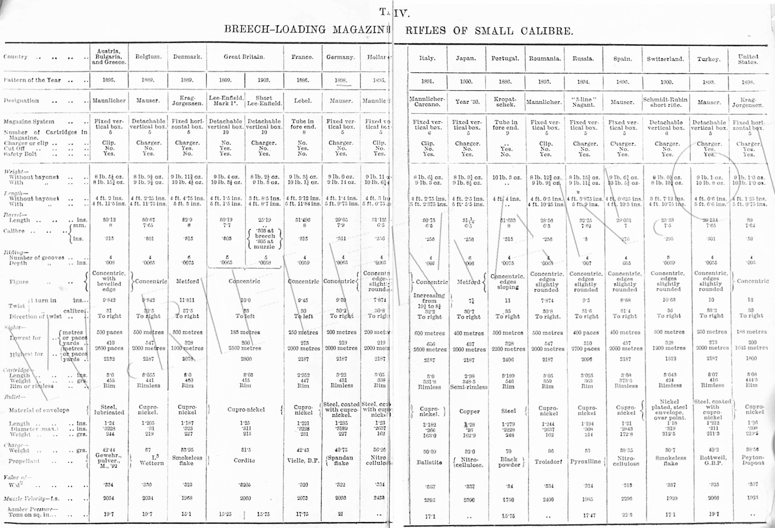
For weights and dimensions see Table IV, Appendix.
Enfield Rifling introduced after the Metford system proved too rapidly eroded.
The introduction of the original SMLE (No.1 Mark 1) was on the 23rd. December 1902, when it was approved and entered into the List of Changes for matériel - Reference Number 11715. That entry is copied below, and affords a detailed description of the rifle and its modification from the previous "Long" Rifle.
11715—Rifle, short, magazine, Lee-Enfield.
23 Dec 1902
(Mark I) - LoC - 3 July 1903
1 July 1903
A pattern of the above-mentioned rifle, as shown in the accompanying drawing, has been sealed to govern future manufacture.
Hover over or Click image to bring up hi-res file and magnifier
The No.1 Mk.1 rifle is about one-and-a-quarter lb. lighter, and
5 inches shorter than the "Rifle, M.L.E., Mark I," (LoC 8117).
The magazine will hold 10 rounds, and is filled by cartridges carried in
chargers (LoC 11753); guides to hold the latter are provided on the bolt
head and body, while the five cartridges held in the charger are swept out
of it by the thumb into the magazine. The bolt and cocking piece may be
locked in the "full cock" and "fired" positions by a
safety catch, and locking bolt, situated on the left side of the body, between
it and the aperture sight; they are held in position by the aperture sight
Barrel — The barrel is smaller
in diameter externally, and 5 inches shorter than that of the L.E. rifle.
it is fitted with a band which carries the block foresight, this is keyed
and pinned to the barrel, and is dovetailed to carry the adjustable barleycorn
foresight (three heights of which will be provided, known as high, normal
and low, and marked "H", "N", and "L", respectively),
to enable variations in shooting to be corrected before the rifle is issued
to the Service. The heights of the high and low barleycorns differ from
the normal by .015 inch.
Backsight— The backsight is fitted with a leaf
pivoted to the bed at the front end; at the rear end is a cap in which the
V is cut. Elevation is given by moving the slide, which rests on curved
ramps on each side of the bed. The leaf is graduated by lines for every
100 yards from 200 to 2,000, the even numbers being marked by figures. The
slide can be set at any 100 yards graduation or intermediate 50 yards elevation,
and is held in position by means of catches engaging in notches on each
side of the leaf. To set the slide, these catches are disengaged from the
notches by pressing the bone studs at each side of the slide. The cap is
joined to the leaf by a vertical dovetail, and it can be given a fine adjustment
for intermediate ranges between the 50 yards elevation afforded by the slide
by means of a vertical screw underneath the cap of the backsight; a small
vernier scale divided to give a vertical movement of .0106 inch being provided
on the left edge of the cap and leaf. Each division on the vernier represents
2 inches elevation per 100 yards. By raising the slide to its highest limit,
2,050 yards elevation can be obtained. The dial sight for long ranges is
graduated from 1,600 to 2,800 yards.
The following particulars show the principal differences in detail between
the short rifle and the M.L.M. and L.E. rifles—
Body— The body is made with charger guide on the
left to receive the charger by which the magazine is loaded, and a stop
on the right which forces the charger guide on the bolt head forward when
the bolt is drawn fully back; it is also arranged to receive the locking
bolt and safety catch to lock the bolt and cocking piece; the cut-off slot
is left in the body for the insertion of a cut-off if required. The left
side of the body is cut away to afford clearance for the thumb of the right
hand when pressing the cartridges from the charger into the magazine. A
cut-off will be supplied for naval service only.
Bolt— The bolt rib is lower, and the handle is
set closer to the body; the bolt cover and extension for the safety catch
is omitted.
Bolt head— The bolt head is made with a slide for the bolt head charger
guide, and has a slot cut in the screwed end of the bolt head, which acts
as a key when stripping and assembling the striker and cocking piece.
Cocking piece— The cocking piece is shorter, and is locked by a locking bolt, the point of which, when the thumb piece is turned back, enters recesses on the left side of the cocking piece and locks it in the full cocked and fired positions. The screw keeper striker is replaced by a nut keeper striker, this is screwed on to a screw, round the shank of which is a spiral spring, contained in a recess in the cocking piece. The nut keeper striker may be pulled to the rear and slightly turned by the finger and thumb, the striker can then be unscrewed from the cocking piece by unscrewing the bolt head; the bolt is thus completely stripped without the aid of tools.
Trigger— The trigger is provided with two ribs, which bear in succession on the lower arm of the sear, and produce a double pull off. The strength of the first pull is 3 to 4 lb., and of the second, 5 to 6 lb.
Butt plate— The sheet steel butt plate is lighter, the butt trap, pin, spring, spring screw, strap and strap screw being omitted.
Magazine— The magazine is slightly deeper in the rear to give more room for the 10 cartridges, and so facilitate loading the second five cartridges from a charger. It is provided with a zigzag platform spring and auxiliary spring. It has a stop clip to keep the right hand cartridge in position, and to enable the platform and spring to be easily removed for cleaning.
Band, inner * — The inner band, which encircles
the barrel at the centre with .002-inch freedom, is fitted inside the fore-end,
and is
held in position by a screw, spiral spring, and washer, so that it supports
the barrel, without holding it rigidly, or preventing ex¬pansion.
Band, outer— The outer band encircles the fore-end and hand-guard
and inner band; it is jointed at the top, and held together by a screw underneath,
which also carries the sling swivel. The swivel screws for the butt, band
and nosecap, are interchangeable.
Nosecap — The nosecap is considerably larger than that of the L.E. rifle; its front end is flush with the muzzle of the barrel, and has an extension in front on which the crosspiece of the sword-bayonet fits, and a bar underneath the rear end to hold the pommel of the sword-bayonet; it is also provided with lugs to carry the swivel and screw, and has high wings to protect the foresight; the muzzle of the barrel has .002 inch freedom in the barrel hole.
Swivels — There are two swivels, one attached to outer band and one to butt, the latter swivel can be attached to lug on nosecap for use in slinging rifle on back when mounted. For Naval Service only, a piling swivel will be attached in this position.
Handguard — The handguard completely covers the barrel, extending from the body to the nosecap; it is in two pieces, being divided diagonally at the centre of the sight bed; the front portion is held in position by the outer band, and its front end fits in a recess in the nosecap; the rear portion is held in position by a spring gripp¬ing the barrel; both portions rest upon the shoulders of the fore-end, being quite free of the barrel throughout. In stripping, the rear hand-guard must be first removed, the front handguard can be pushed back clear of the nosecap after the outer band has been removed. The rear portion is fitted with a backsight protector, consisting of two upstanding ears, which protect the cap of the backsight when the latter is adjusted for short ranges.
Stock, fore-end — The stock, fore-end, extends to within 1/8-inch of the muzzle of the barrel; it is free in the barrel groove throughout, excepting about ½ inch in front and rear of the inner band, and under the knoxform at the breech end. It is fitted with a keeper plate let into the breech end, into which the squared end of the stock bolt fits, to prevent the stock bolt turning and the stock butt becoming loose.
Stock, butt — The stock, butt, is issued in three
lengths, one ½ inch shorter and one ½ inch longer than the normal, and
marked respectively S and L. It is fitted with a sheet steel butt plate
without butt trap, as the oil bottle and pull-through are not carried in
the butt. It is bored longitudinally with four holes for lightness, and
is provided with a marking disc screwed into the right side. The stock bolt
is shorter, and is squared at the front end to fit the keeper plate.
In stripping the rifle it is necessary that the fore-end should be first
removed before turning the stock bolt.
Particulars relating to rifling, sighting, weight,
&c.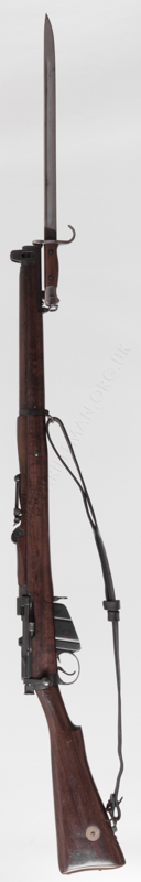
Length of barrel 25 3/16 inches. Calibre .303 inch.
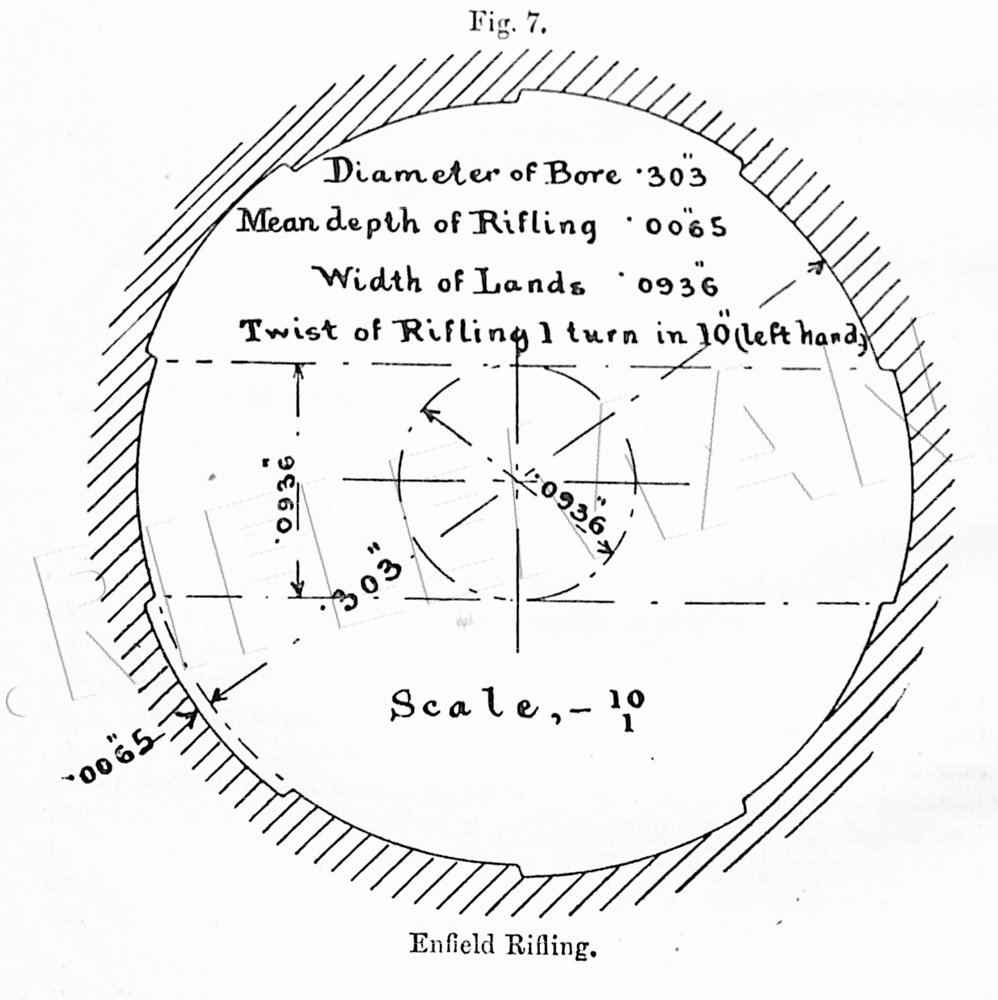
Rifling Enfield
Grooves, number 5
depth at muzzle .0065 inch.
depth at breech, to within
14 inches of muzzle .005 inch.
Width of lands .0936 inch.
Twist of rifling, left-handed 1 turn in 10 ins.
Sighting system Adjustable barley
corn front sight, radial back sight.
Distance between barleycorn
and back sight, V 1 ft. 7 5/32 ins.
Length of rifle 3 ft. 8 9/16 ins.
Length of rifle with sword-bayonet 4 ft. 8 11/16 ins.
Length of sword-bayonet (over all) 1 ft. 4 7/8 ins.
Length of sword-bayonet blade 1 ft. 0 1/8 ins.
Weight of rifle, with magazine empty 8 lb. 2½ oz.
Weight of sword-bayonet 1 lb. ½ oz.
Weight of sword-bayonet scabbard 0 lb. 4½ oz.
Ammunition same as for M.L.E., M.L.M., M M., and M.E. arms.
The following components are special to this rifle—
Components
Barleycorn foresight— Guard, trigger
Normal Guard, hand, front
High Guard, hand, rear
Low Guard, hand, front cap
Barrel Guard, hand, rear sight
Block, band, foresight protector
Body Head, with catch, slide,
Bolt sight leaf (2)
Bolt head Key, block, band, foresight
Bolt head charger guide Leaf, sight, back
Butt plate Locking bolt
Band, outer Locking bolt stop pins (2)
Band, inner Locking bolt safety catch
Bed, sight, back Magazine case
Bolt, stock Nosecap
Clip, stop, magazine Nut, keeper, striker (with pin)
Cocking piece Nut, screw, back, nosecap
Cut-off t
Extractor t In rifles for naval service only.
Pin, axis, leaf, sight, back Screw, fine adjustment, sight
Pin, fixing, bed, sight, back leaf
Pin, fixing, block, band, Screw, keeper, slide, fine
foresight adjustment, leaf, sight, back
Pin, fixing, stud, head, catch, Screws, nosecap
slide, sight, back Back
Pin, joint, band, outer Front
Plate, dial, sight Screw, nut, keeper, striker
Platform, magazine Screw, spring, aperture sight
Rivets, handguard, rear, sight Screw, spring, sight, back
protector, side Screw, stop, charger guide
Rivets, handguard, cap and Sear
sight protector, top (3) Slide, sight, back
Spring, aperture sight Slide, fine adjustment, leaf,
Springs, catch, slide, sight, back
sight leaf (2) Striker
Spring, nut, keeper, striker Stem, swivel, butt
Spring, platform, magazine Stock, butt—
Spring, auxiliary, platform, Normal
magazine Long
Spring, screw, band, inner Short
Spring, sight, back Stock, fore-end
Strew, band, outer, and Stud, clip, stop, magazine
swivels, butt and piling Trigger
Screw, band inner Washer, spring, band, inner
Screw, guard, back Washer, pin, axis, sight, back
Screws, bed, sight, back— Washers, rivet, fore-end; cap,
Front spring, and sight protector,
Back handguard (7)
Screw, dial sight, fixing
The pattern 1903 sword-bayonet (LoC 11716, 11717), is used with this rifle.
Below: an Enfield drawing of the No.1 Mk.1 fore-end and barrel with sights mounted.
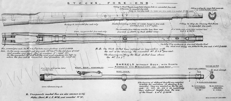
* Of the major modifications, from the Long rifle to the Short, at least three required patents, namely the safety catch, the barrel ring and the rear-sight, the latter illustrated above. These consecutive patents were applied for in 1902, on behalf of the Enfield factory, by Messrs. Watkin and Speed.
6743. Watkin, H. S. S., and Speed, J. J. March 23.

Sights.—Relates to back sights, in which the leaf is gradually elevated
for range by a slide which travels down the leaf and along the top of a
curved bed. Fig. 1 shows a side elevation, and Fig. 2 a plan. The leaf h
is hinged at i, and consists of a graduated bar having teeth along its edges
to engage with spring catches on the slide m, which rests on the top surfaces
of the curved bars d. The leaf bar h is graduated for hundreds of yards
range, the necessary ad¬justments for intermediate ranges being effected
by the screw v1 which moves the notched bar f on the bar h.

6744. Watkin, H. S. S., and Speed, J. J. March
23.
Barrels ; stocks.—Relates to means for attaching the barrel to the
stock, and consists in the employ¬ment of rings a, Figs. 1, 2, passing
over the barrel and hiving flats e to grip the barrel as soon as the rings
are drawn towards the stock by the spring-supported screws d.
Breech actions, sliding breech-block.—Relates to safety devices for
bolt guns. Fig. 3 shows the gun in elevation, Fig. 4 the breech-bolt and
hammer detached, Figs. 5, 6, the hammer safety,
After the design had been finalised, trials completed, the rifle officially adopted and the initial production commenced of the first batch of rifles, a bronze casting was made in miniature and a number of these were presented to key members of the design and production teams.
An example of the cased award is shown below, followed by a rotational image of the rifle itself.
.jpg)
The next image can be rotated and zoomed, either as initially loaded or full-screen for higher definition.
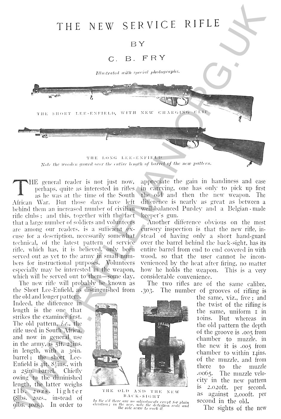
In 1905, C.B.Fry wrote in his famous sporting and social magazine of the "New" rifle being introduced.
Click the image below for a searchable flip-page facsimile of the article
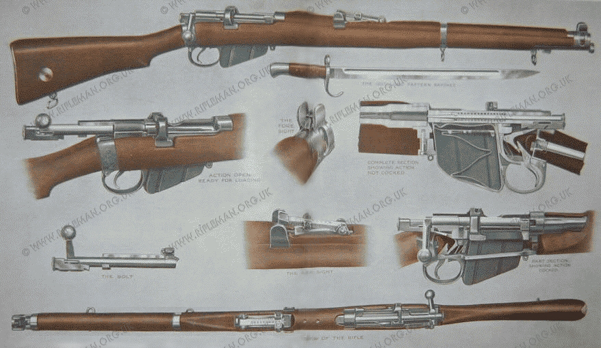
The cross-sectional drawing below is of the 1907 Mark III rifle.
Below: A Birmingham Small Arms Company drawing of their "GreatWar" ( 1914-18) No.I Mk.III S.M.L.E.
This rifle was approved and entered into the List of Changes on 26th. January 1907
The S.M.L.E. became the Rifle No.1, in its various marks, subsequent to the introduction of a new system of nomenclature, in May 1926, in which succeeding rifle designs were designated by number.
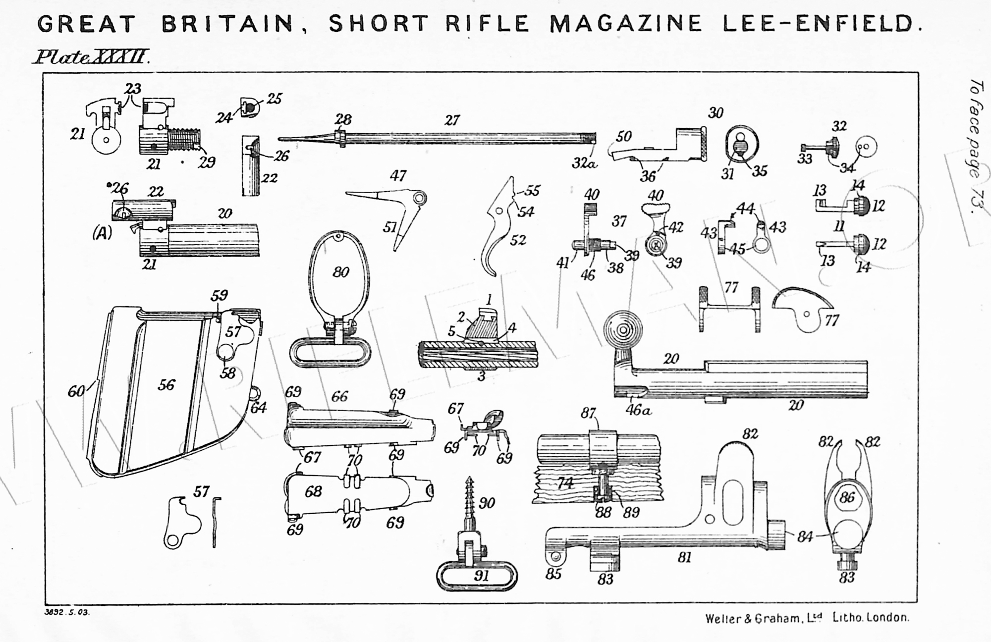
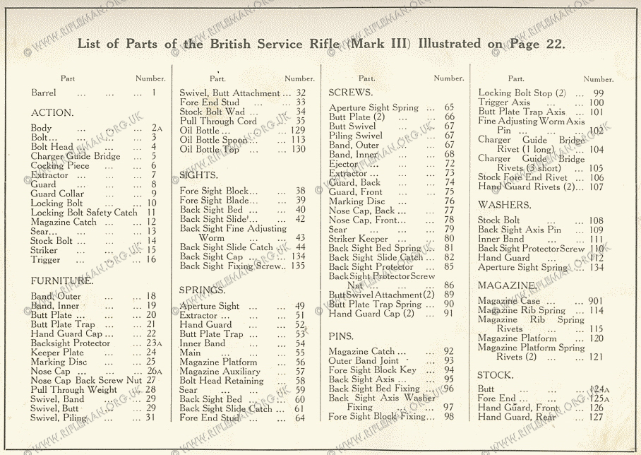
And a photograph taken at that time of the component parts
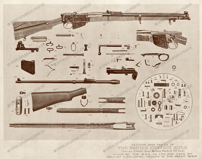
with, for the definitive component nomenclature, the associated numbered parts list below
To view the complete Small Arms drawings (S.A.I.D.)
for the No.1 Mk.III, III* and No.2 rifles
and components
click on either of the next two images.
An alternative parts diagram and notated list from the 1915 Hythe Musketry Course manual with, below that, the stripping and re-assembly instructions from the same manual.
By way of comparison, we illustrate the parts diagram and listing of the preceding "Long Lee-Enfield" -
more properly notated as the C.L.M.L.E. or Rifle, Charger Loading, Magazine, Lee-Enfield.
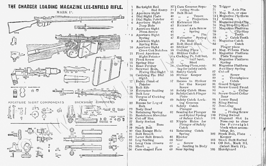
The 'charger loading' refers to the "loading-bridge" later added to the rear of the action of the original Lee-Enfield Magazine Rifle shown at the head of this article, which weapon could not be clip-loaded. A vertically machined T-slot in the bridge of the modified rifle - as above - permitted the use of the now familiar 5-round loading clip. The clip, itself loaded with five .303 cartridges, was fed down into the slot in the bridge until it rested on the rear of the magazine. The rounds were then pressed down into the magazine by the thumb. A curved cut-out, in the LHS of the action body side, allowed the thumb to press the cartridges sufficiently low into the magazine to lock the last round in place. On closing the bolt and chambering the top round, the now empty clip was thrown clear of the rifle.
The design was highly problematic for the left-handed firer and, in common with such every-day tasks as writing and using scissors, recruits were obliged to use these weapons right-handed. The strictness of such teaching, in all walks of formative life, led to many apparently ambidexterous people. Truthfully, all those with master left hands were presented with little alternative but to conform, and their resultant capabilities with both hands led to their, for all practical purposes, effective ambidexterity. My own father could pen the most beautiful copper-plate writing with either hand, either both left to right, or even as a mirror image on one piece of paper at the same time. Such discipline can lead to almost unlimited attainment.
Probably the most authoratitive write-up on the S.M.L.E. No.1 Mk.III, and particularly its production, is the section in the post-WW1 history of the Birmingham Small Arms Company's activities during the Great War - published ca.1920. We illustrate the extracted piece below as a searchable flip-page booklet.
These text-searchable documents can be viewed with vertical scrolling
or as flip-pages by clicking the appropriate icon where shown.
Depending upon the number of pages they may take a few moments to load.
Double tap tablet or click ![]() for full page display.
for full page display.
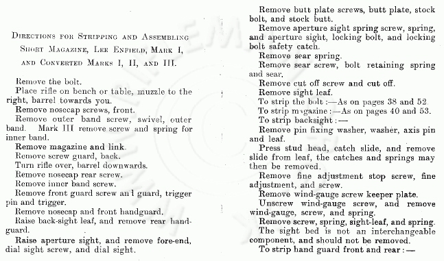
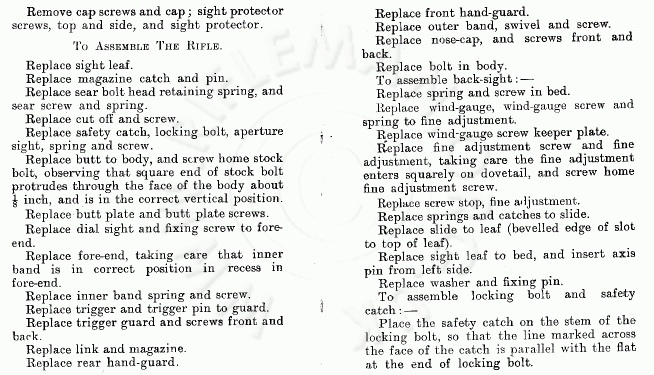
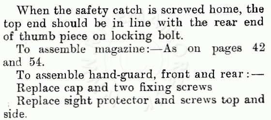
Perhaps the definitive description of the S.M.L.E. Mk.III in military service terms was included in the 1904 and 1909 Text Book for Small Arms.
The text and drawings are illustrated in the following PDF of the 1909 version.
A good description of the Mk.III S.M.L.E. and its usage is to to be found in a 1942 Canadian training manual; this is replicated below.
This is in the form of a text-searchable flip-page document that may take a few moments to load.
Double tap tablet or click ロ for full page display.
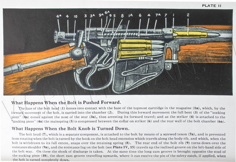
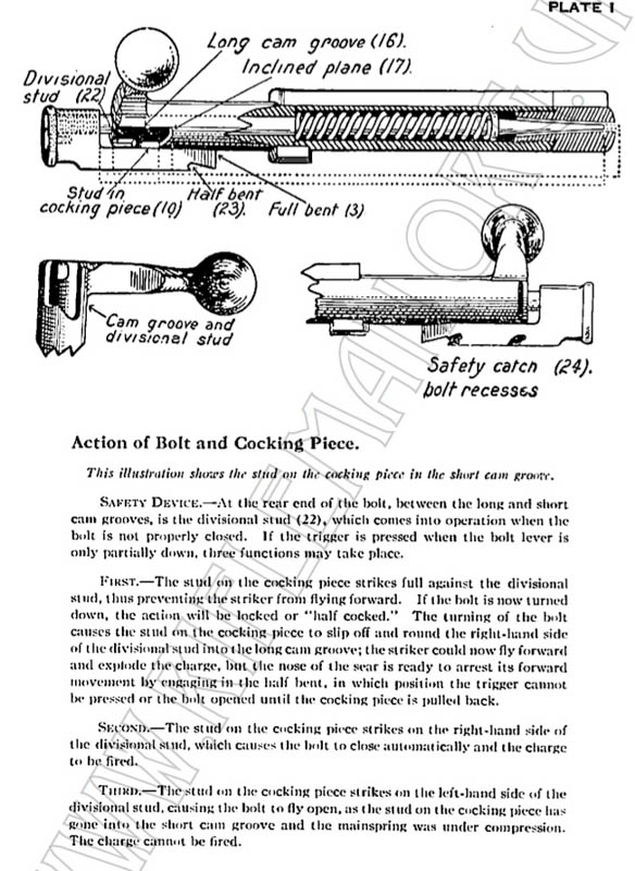
The pages in the manual carrying the coloured drawings of the rifle's cut-away action are shown below for clarification.
The first of the three drawings illustrates the closing of the bolt to chamber a round.
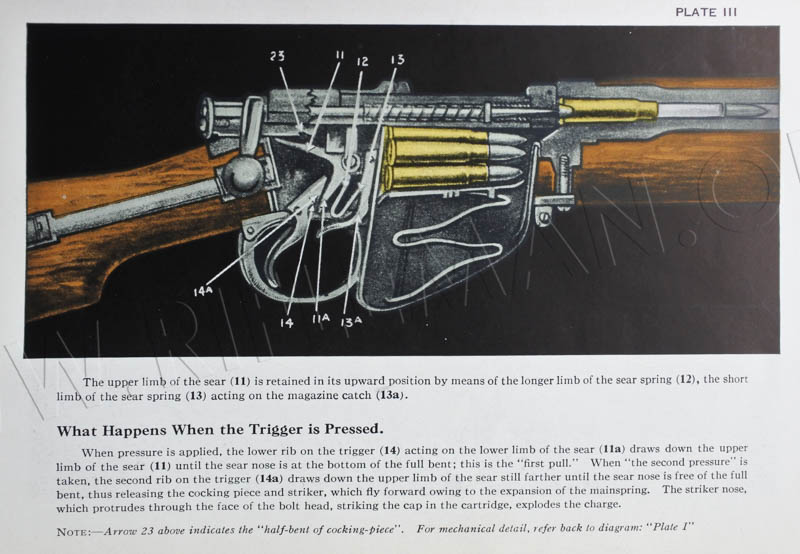
The second drawing details the action of pulling the trigger.
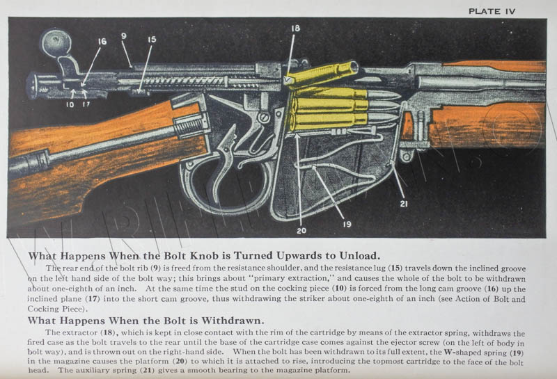
And the third drawing shows the ejection of the fired cartridge case as the bolt is opened and drawn back.
Detail of the bolt and notes on its function are shown in the next image.
See the Pattern 1914 .22RF training version of the No.1 Mk.I rifle shown on this page
and the Mk.III .22RF training Lee-Enfield equivalent to the .303"CF model illustrated on this page
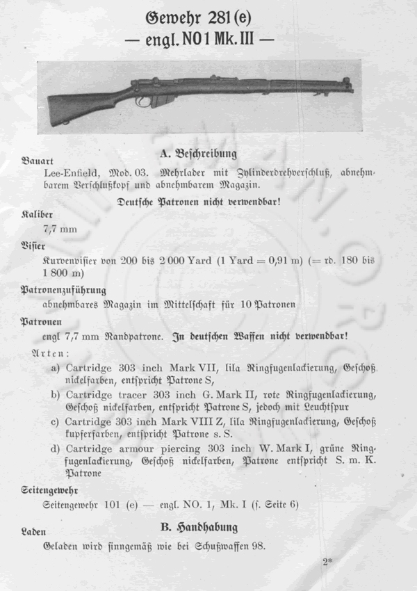
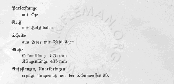
An interesting addition to literature on the S.M.L.E. are the relevant pages from the 1940 German manual of British Smallarms. If you read German you will obtain the greatest benefit, but enough text is effectively English that it is worthwhile illustrating.
The 60 page manual covers every small arm then in use by British forces including pistols, rifles, machine guns, and even the Mills Grenade.
The entire manual can be viewed via the above link or clicking the images below..

For the true scholar, there is no more authoritative source of definition and history of the S.M.L.E. Mk.III than the notes on the rifle in the 1929 British Textbook of Small Arms. We therefore include these here.
CHAPTER I—SECTION 3
THE BRITISH SERVICE RIFLE
The photograph below is that which accompanies the following material in the 1929 Textbook of Small Arms

The short, magazine, Lee-Enfield rifle was approved on 23rd December, 1902, to take the place of the magazine Lee-Metford and magazine Lee-Enfield (familiarly known as the " long rifle "), various marks of which had been the service weapon since 1888. Of the rifle, S.M.L.E., there are six marks, Marks III, III*, and IV now being in use.
Mark I .. Approved 1902. New rifle.
Mark II .. A conversion from long rifle. Similar to Mark I.
Mark III .. Approved 1907. Improvement on Mark I.
Mark IV .. Conversion from old marks. Similar to Mark III.
Mark III* .. Approved 1918. No cut off. No long-range sights.
Mark V .. Provisionally approved 1922. Improvement on Mark III. Peep-
hole backsight. (Superseded before being produced in quantity.) Mark VI .. Improvement on Mark V. Not yet issued.
All the above marks have the Lee bolt action, similar to that approved in 1888 for the Lee-Metford magazine rifle, Mark I. Details of the Mark III and Mark III* are as follows. (See Fig. 11 and Plate XI.)
The drawing below relates to the following description.
The bolt (1) is simple in construction. It is cylindrical and has a bent lever at the rear end, terminating in a round knob for convenience in handling. The shape and position of the lever are very convenient for rapid manipulation. On the right side of the bolt cylinder is formed a solid rib (2), which works in a slot in the rear of the body and acts as a guide when the bolt is worked backwards and forwards. On the opposite side to the rib, and having its rear face level with the rear face of the rib, is a solid lug (3). The lug and the rear face of the rib engage against appropriate bearings when the bolt is locked and support the bolt on firing. The disadvantages and advantages of having the lugs so far removed from the face of the bolt-head have been discussed in the previous chapter. The rear faces of the rib and lug are cut on a screw pitch corresponding to the slope of their seatings on the body. On turning down the bolt this gives the necessary leverage to force the cartridge home. The lug working in its screw-pitched recess in the body provides the leverage for primary extraction on turning up the bolt. The bolt-cylinder is bored out to take the striker (4) and mainspring. The rear part of the boring is constricted to the diameter of the striker, to form a seating for the rear of the mainspring and to act as a guide for the striker. Underneath the rear end of the bolt-cylinder is a recess (5) formed by a long groove on the right and a short groove on the left, connected together in front by a cam-shaped face and separated by a stud (6) . On raising the bolt lever the cocking-piece stud (7), which is resting in the right-hand or long groove, is forced backwards by the cam-shaped face until it rests in the left-hand or short groove, thus partially compressing the mainspring and withdrawing the point of the striker from the face of the bolt-head. This is necessary to prevent the striker point from firing the cap of the next cartridge as it is fed upwards from the magazine and pushed forward into the chamber.
The bolt-head (8) has a tenon which screws into the bolt-cylinder. On it is a solid projection which has a hook (9) on its right side which engages with a rib on the right side of the body and prevents the bolt-head from turning with the bolt-cylinder. On the side of the bolt-head is a hole to allow for the escape of gas in event of a blow-back or burst case. The projection on the bolt-head is slotted to take the extractor, which is a short steel bar with the usual claw at the end. It is pivoted on a screw at the rear of the slot and is kept up to its work by a small V-spring let into the slot above it.
The striker is in one piece and has a collar (10) against which the front end of the mainspring bears. The front face of the collar seats against the rear end of the bolt-head tenon in the fired " position and thus limits the protrusion of the striker. Originally
there was, in front of the collar, a small stud which fitted into a recess cut for it in the rear of the bolt-head tenon. This stud was later discarded, but both the modified and unmodified types of striker are still in use in the service. The end of the striker is screw-threaded for attachment to the cocking-piece (11).
The mainspring (12) is of coiled steel wire set to a length of 32 inches.
The cocking-piece has a long tongue projecting to the front and lying against the under side of. the bolt when it is assembled. The front end of the tongue forms the full bent (13) and a groove cut across it the half bent (14). A stud (7) on the upper side of the tongue works in the two grooves already mentioned in the rear of the bolt-cylinder. On the left side the tongue is recessed in two places for the locking-bolt to engage in. The rear of the cocking-piece was originally formed with a circular projection, cut away on the left-hand side and roughened to serve as a grip for finger and thumb when cocking without operating the bolt. The Mark III* rifle was fitted, as an alternative to facilitate manufacture, with a cocking-piece which had its rear end formed as a flat piece, grooved on each side to give a grip for finger and thumb. Both these types of cocking-piece are now interchangeable in the Marks III and III*.
The bolt may be easily stripped for cleaning and examination. The striker keeper screw (15), which retains the striker in position in the hole drilled and tapped for it in the rear portion of the cocking-piece, having been removed, the bolt-head is unscrewed. Those strikers which are fitted with a stud on the front face of the collar can be unscrewed by means of the bolt-head, but to avoid the possibility of damage to the bolt-head tenon this method should not be employed, and the special tools with which armourers are provided should be used.
The body is cut away on the right side for the greater part of its length to allow the projection on the bolt-head to work backwards and forwards. The hook on the projection of the bolt-head engages in a slot or rib, which is cut away at the rear end just sufficiently to allow the hook on the bolt-head to be free. There is a small retaining catch forming a continuation of the rib at this point. When the bolt is drawn back as far as possible the hook can be forced up over this catch and the bolt removed from the body. The retaining catch is a small spring secured by the rear axis screw on the right side of the body. The rear of the body does not form a complete cylinder but is slotted out at the top to afford passage for the rib on the bolt and at the bottom for the bolt lug and cocking-pieces. The right-hand side of the rear of the body forms the right resistance shoulder for the rib on the bolt, and opposite this on the left side is the slot into which fits the bolt-lug, the rear face of the slot forming the resistance shoulder on this side of the body. It is cut on a screw pitch to assist in forcing the cartridge home in the chamber and in the final compression of the mainspring when the bolt is turned down into the locked position for firing. The recess for the lug is at the rear end of the body, opposite the resistance shoulder, the entrance to it is cut on an incline in the usual way to give the leverage necessary for primary extraction.
In front of the resistance shoulder, at a sufficient distance to give clearance for the bolt-head projection when the bolt is being removed, a charger-guide, in the form of a bridge (16) is riveted to the left and right sides of the body. Immediately in front of the charger-guide, the left side of the body is cut away in a semi-circle to allow the thumb to sweep the cartridges out of the charger into the magazine. The front end of the body is a complete cylinder into which the barrel screws. As no space has to be provided for the lug recesses the bolt-head enters a little distance only into this cylinder, which is not much recessed and is readily cleaned. Beneath the barrel chamber the action body is sloped off (17) to provide a way or guide for the cartridges entering the chamber from the magazine. The right side of the body is slotted to take the cut-off. There is no tang as in Continental actions. The place of the tang is taken by a socket (18) which is part of the body and projects downwards. Into it the butt fits and in the centre of it is a hollow, threaded boss (19) for the stock-bolt (2). The rear end of the body, including the upper surface of the socket, is grooved to allow passage for the lug and cocking-piece tongue. The usual opening beneath the body is provided for the magazine.
At the rear end, on the left of the body, two holes are drilled for the locking-bolt (21) and locking-bolt safety-catch (22). The locking-bolt is a stem, fitted with a roughened thumb-piece by which it may be actuated. The stem fits into a hole in the body leading into the groove for the cocking-piece tongue. The end of the stem is cut away so that when the thumbpiece is in the forward position the cut-away portion is level with the floor of the groove for the cocking-piece tongue and the cocking-piece can pass over it. When the thumbpiece is drawn to the rear the solid portion of the stem rises in the groove and engages an one of two recesses cut in the cocking:piece tongue, according to whether the latter is in the cocked or fired position. The bolt can thus be locked fired, or cocked. When the stem of the locking-bolt engages in the front, or cocked position recess, it draws back the cocking-piece slightly, removing the bent from contact with the nose of the sear. On the stem of the locking-bolt, close to the thumbpiece, is cut a steep-pitched thread (23). On this thread works the arm of the safety-catch. On the end of this arm is a short stem which fits in the hole entering the bolt-way of the body. When the thumbpiece of the locking-bolt is in the forward position this stem is within its hole and clear of the bolt in the bolt-way. When the thumbpiece is drawn to the rear, the threads on the locking-bolt stem and safety-catch arm push the stem forward so that its end enters the short groove on the end of the bolt and prevents the latter from being rotated and drawn back. By the combined action of locking-bolt and safety-catch both cocking-piece and bolt are positively locked against any possibility of accidental opening or discharge.
The ejector is a small screw which projects slightly into the bolt-way on the left side. On drawing back the bolt the back edge of the rim of the cartridge case catches against the end of this screw and is thrown out of the rifle to the right. In practice this action only take s place in the case of a bulletted round, when the case is held on the bolt face until the bullet is clear of the breech. An empty case, being shorter and therefore being clear of the barrel sooner, is normally thrown out to the right by the action of its rim frictioning against the sloping portion of the groove hollowed out in the left side of the body immediately behind the breech.
The trigger mechanism is on the double-pull system already described in the account of Continental rifles, but differs from them in most particulars, save for the provision of two ribs (24) on the upper part of the trigger. The sear (25) is a two-armed, bell-cranked lever, pivoted to the projection beneath the body on the same screw which holds the retaining catch. It is pressed to the rear and upwards by a U-shaped spring (26) which also serves to keep the magazine-catch up to its work. The long, upper, arm passes through a hole in the body into the groove for the cocking-piece tongue, and engages with the full-bent on the latter when the bolt is pushed forwards. The short arm projects downwards. The trigger is pivoted on a pin which passes through the trigger guard (27). The two ribs are on the front surface of the upper part of the trigger. On pressing the trigger the lower of the two ribs engages with the short arm of the sear and causes the latter to revolve on its axis until the end of the long arm has come close to the edge of the bent. The pull during this movement is light as the rib is close to the trigger pivot and great leverage is obtained. The fulcrum is then transferred to the upper of the two ribs which, being further from the pivot, affords less leverage, and a stronger pull is therefore necessary to make the sear move the small remaining distance which releases the cocking-piece and allows it to fly forward. The motion imparted to the sear by the motion of the trigger acting through its upper rib is, however, more rapid, and the sear is thus drawn smartly off the bent.
The action of the bolt mechanism has already been indicated in the description of the parts. The complete sequence is as follows :-
On raising the bolt-lever the cocking-piece is prevented from turning with the bolt by the fact that the tongue is engaged in the groove in the body. The bolt-head is prevented from turning by its hook engaging with the rib on the right side of the body. As the bolt is turned the cam-face at the end of the two grooves on the rear of the bolt forces back the stud on the upper side of the tongue of the cocking-piece. This draws the end of the striker clear of the end of the bolt-head and partially compresses the mainspring. As the turning movement continues the sloping face of the lug working against the sloping
face of the recess in the body causes the whole bolt to move to the rear, effecting primary extraction. When the bolt has been turned as far as it will go the rib touches the left side of the body and is opposite the gap in the rear of the body. The lug is now in the groove for the cocking-piece. The bolt can be drawn back until the projection on the bolt-head strikes against the resisting shoulder. This acts as a retaining arrangement. The stud on the cocking-piece tongue has now fallen into the recess in the front end of the short groove on the bolt and the cocking-piece cannot revolve and is retained in position for entering its groove in the body. On pushing forward the bolt the full bent of the cocking-piece engages the end of the sear and the mainspring is further compressed. As the bolt is driven forward the stud between the long and short grooves on the bolt passes the stud on the now stationary cocking-piece. On turning down the bolt, the bolt is forced forward by the action of the sloping faces on the rear of the lug, and the rib working against their bearings on the body. In the complete action of closing the bolt the free forward travel is 3 inches, the travel after the sear has engaged with the bent when the pressure of the mainspring has to be overcome, is ½-inch, and the final forward movement, on turning down the lever, finch. When the action is cocked the stud on the cocking-piece tongue lies in the long groove in the body and the cocking-piece and striker are free to fly forward when the sear is released from the bent by pressing the trigger. Should the trigger be pulled when the bolt is not completely closed the stud on the cocking-piece tongue strikes against the stud between the two grooves on the bolt and either causes the bolt to .close, automatically, before the striker point reaches the cap of the cartridge, or else the two studs meet full face and the striker is prevented from flying forward. If the action is then closed by hand the sear falls into the half-bent and the action is locked owing to the two studs lying side by side, preventing the rotation of the bolt. It is possible to cock the action fully by drawing back the cocking-piece.
The magazine (28) is a detachable sheet-steel box, strengthened by two flutings on either side. It contains ten cartridges in two columns which are fed up as required by the action of a zig-zag ribbon steel spring (29). The platform (30) is so formed that the left side is higher than the right. The left-hand column of cartridges is thus presented to the bolt first and then the right-hand column, cartridges being pushed forward alternately from each column until the magazine is empty. The sides of the rear end of the box are extended slightly upwards and turned in to retain the cartridges. In the No. in (stamped with the figure 4) magazine there are small inturning projections made by turning over the top of the sides of the box in front. These serve to keep the platform in position when the magazine is empty. In earlier marks of magazine a stop clip is pivoted on the right side of the box, in front, which helps to keep the platform in position when the magazine is empty and keeps the bullet of the upper cartridge of the right-hand column in position when the magazine is full. This clip can be drawn down to the front when the magazine has been detached from the body, and the platform and spring can be withdrawn for examination and cleaning. The spring is secured to the No. 3 platform by a tongue of metal turned over on the right-hand side and by two rivets. In earlier marks it is secured by two tongues of metal on each side. Downward turned tongues of metal on the front and on the left-hand side at the rear of the platform serve as positioning guides. A small turned down tongue on the right side at the rear serves the same purpose. At the back of the box is a rib in which is cut a tooth (31) to engage in the magazine retaining spring catch. In the No. 1A and 1B (stamped 3 and 4) magazines there is also a small auxiliary spring which bears against the front of the trigger guard. Into the front of the box is hooked and secured the magazine platform auxiliary spring (32) which serves to keep the front end of the platform at a proper angle when the magazine is full and also protects the front of the box from being dented by the points of the bullets.
The cut-off is pivoted to a vertical screw in the projection on the right side of the body. It works in a slot parallel to and below the rib on the body for the bolt-head hook. It is provided with a cylindrical thumbpiece, bored out for lightness and ribbed on top for the thumb to grip. It is spring-tempered and set to press upwards, a small projecting flat on the upper surface acting as a catch against the side of the body and holding the cut-off open or shut. In the shut position the cut-off holds down the cartridges in the magazine out of the path of the bolt and acts as a platform for single loading. The hole in the rear of the cut-off is for convenience in manufacture only. In the Mark III* rifle there is no cut-off. In none of the marks is any provision made to indicate that the magazine is empty, as is provided in the United States rifle and in some Continental arms.
The trigger guard is attached to the body by a screw (33) passing up through a collar (34) let into the fore-end in front of the magazine, and by a small transverse screw (35) passing through ears on the bottom of the socket of the body.
The barrel, which screws into the body in the usual manner, is strongly reinforced at the breech end, which is formed into a flat on its upper surface known as the Nock's or " Knox " form (36), from an old-time gunmaker named Nock, who first devised this method of ensuring the correct breeching up of barrel to body necessary to bring the sights vertical. It is 25.1 inches long overall and weighs 2 lbs. 21 ozs. This is the lightest barrel used in any service arm.
The rifling is of the Enfield figure with five grooves of -0065 inch mean depth. The width of the lands between the grooves is -0936 inch. The twist of the rifling is one turn in 10 inches left hand. The left-handed twist was originally adopted in order to compensate for the drift due to the rotation of the earth in the Northern hemisphere. It also has the effect of twisting the butt of the rifle away from the firer's cheek instead of against it.
The foresight (37) is of the " blade " pattern and consists of a plate dove-tailed into the foresight block (38) at right angles to the axis of the barrel. It is capable of lateral adjustment. The foresight block is formed with a band which fits the barrel and is kept in position by a key and cross-pin. It is set approximately • 015 inch left to counteract the lateral throw of the rifle due to vibrations set up on firing. The backsight (39) is attached to a bed (40) which encircles the barrel, to which it is fixed by a cross-pin in the middle. It is also supported by the sight spring screw. The sides of the bed are raised to form a ramp (41). The leaf (42) is a solid piece of steel pivoted to the bed in front and kept in position by a spring fitted into the bed. It can be turned over on to the hand guard and rebounds into correct position when it is brought past the vertical. It is graduated from 200 to 2,000 yards. On the top left side of the leaf are lines representing every 25 yards. On the top right side the lines represent every 100 yards. The odd figures from 300 to 1,900 yards are omitted. A slide (43) fitted with a spring catch and a fine adjustment worm-wheel (44) enables the sight to be set at any elevation. The right side of the leaf is cut with screw-thread notches, and in these the fine adjustment worm-wheel engages. By pressing a catch on the left side of the slide the fine adjustment is released, and the slide may be moved quickly along the leaf by the action of the thumb only. The periphery of the worm-wheel is divided by 10 thumb-nail notches, the distance between each notch representing 5 yards in range, i.e., 5 notches equal 25 yards, or one division on the left side of the leaf. One complete revolution of the fine adjustment worm-wheel moves the slide 50 yards.
A wind gauge was originally fitted on the rear end of the leaf, but has been discarded. It was held in position by the wind-gauge screw. The scale was marked in divisions representing 6 inches deflection on the target at 100 yards. Each quarter-turn of the wind-gauge screw represented 1 inch of deflection for every 100 yards of range at which the sight was set. At each quarter-turn a friction spring engaged in a nick inside the head of the screw, checking its rotation. A U-shaped notch was cut in the top edge of the slide, and the face was roughed to prevent the reflection of light.
In the Mark III* and in the later Mark III rifle there is no wind gauge. Its place is taken by a cap which is attached to the leaf by means of a screw. It is provided with a U-notch and roughened on the face. There are two patterns of backsight cap which differ slightly in form.
Long-range sights were provided in the earlier Mark III, giving elevations from 1,700 to 2,800 yards. The backsight consisted of an aperture attached to the left side of the
body. It was carried on a bar terminating at the upper end in a cup-shaped button
through which a peep-hole was bored. It was pivoted on the stem of the locking bolt and kept in position by a spring. The foresight, known as the dial sight, was attached to the left side of the fore-end, and consisted of a dial on which the ranges were marked, a pointer, and a bead which acted as a foresight.
No long-range sights are fitted to the Mark III* rifle or to the later Mark III.
The stock is in two pieces. The fore-end (45) is held to the barrel by a nose cap (46) and outer band (47), which are fitted with swivels. The swivel of the nose-cap is a piling swivel, i.e., cut away in the centre. A swivel is also fitted on the butt. Naval service swivels are made slightly larger than for land service. The barrel being comparatively light, accuracy is liable to be detrimentally affected by a badly fitting fore-end. In the assembled rifle there are three important metal-on-wood bearing points where even bearings must be ensured. They are as follows :-
(1) The thrust of recoil is received by the stock, through the medium of the sear lugs on the body, on the resistance shoulders formed a little in front of its rear end. It is essential that the thrust should be taken up evenly on both sides.
(2) The barrel must be held firmly down on the fore-end at the reinforce. This is effected by the fore-trigger-guard screw, which is fitted with a collar which limits the amount of " crush " which can be obtained on the wood by tightening. It must be noted that in the case of a shrunk fore-end there is a danger of the screw being screwed up tightly against the collar without pulling the barrel down tightly on the fore-end. Careful fitting is therefore necessary. It is also important to remember that, since the trigger is mounted on the trigger guard, a loose fore trigger-guard screw may affect the " pull-off " of the rifle by allowing the front end of the trigger guard to drop, and thus slightly affecting the relative positions of the trigger and the tail of the sear.
(3) The barrel is caused to bear lightly on the woodwork z inch in rear of the inner
band (48) by means of a spring acting through the medium of the latter.
Between (2) and (3) the woodwork is hollowed out so as to be clear of the barrel, and from the inner band forwards the barrel is held away from the fore-end by the fore-end spring stud, the hole in the nose-cap being slightly oval in form to give the necessary clearance.
The foregoing is a brief description of the service stocking. For match shooting under N.R.A. conditions, with private rifles, certain other methods have been evolved. These other methods have for their object the stiffening of the barrel and the damping of the vibrations set up on firing in order to attain a relatively high standard of accuracy for the special conditions of target shooting. They consist, briefly, in adopting some means of packing the barrel between the fore-end and fore-hand guard. The service stocking was evolved with the object of ensuring a consistently satisfactory standard of accuracy under service conditions.
A backsight protector formed with two upstanding ears, roughened on top so as not to reflect the light, is let into the fore-end and secured by a vertical screw and nut.
The nose-cap completely encircles the barrel at the muzzle and is provided with a tang which projects backwards under the fore-end and carries the piling swivel at its rear end. Immediately in front of the piling swivel is a sword bar for the attachment of the pommel of the bayonet and in front below the muzzle is a boss on which the ring of the bayonet cross-piece fits. The sword bayonet is thus fixed underneath the rifle to the nose-cap only and does not touch the barrel. The nose-cap is provided with high wings roughened on top, which protect the foresight. It is pierced on either side beneath the wings for lightness.
The hand-guard (49) extends the full length of the barrel and is divided into two parts by a saw cut opposite the backsight bed. This is for convenience in fitting and removing. The rear portion fits over the barrel and is held in position by means of a spring riveted on to it. The front end of the hand-guard is strengthened by a sheet steel cap which fits under a recess in the nose-cap. A groove is cut in the correct position for the jointed outer band, a slot being formed to give clearance to the hinge. The hand-guard does not touch the barrel as the groove is of greater diameter than the barrel. An inner band is carried permanently on the barrel ; it is grooved out so as to touch the barrel in two places. and is fixed in the groove of the fore-end in rear of the lower band by means of a screw, the head of which bears against a strong spiral spring.
The butt is attached to the socket on the action body by means of a stock bolt (20) that is inserted through a hole drilled longitudinally from the butt end. It is made in three ordinary lengths, long and short butts being marked by the letter L or S stamped on the wood on the top of the butt. For special use during the Great War, butts shorter than the ordinary short butt were made. These were termed " bantams," and stamped with the letter " B."
The butt plate is of brass, forgeable alloy or malleable iron. It is finished polished or zinc electro-plated according to the materials employed in manufacture. It is fitted with a trap for the insertion of oil bottle and pull-through. A marking disc is fixed with a screw to the right side. The " grip " is of a special " semi-pistol " shape.
The Rifle, Short, Magazine, Lee-Enfield Mark V was an improvement on the Mark III, but although a certain number were produced in 1925 none were issued, and it was later discarded in favour of the more fully developed Mark VI. The Mark V differed from the Mark III in several particulars, the chief of which were (1) the adoption of an aperture backsight located on a specially-designed bed on the body behind the bridge charger guide ; (2) the making of the hand guard in one piece completely covering the barrel.
The Mark VI is the outcome of experiment, since the Great War, but as yet has not been produced in quantity. At the present juncture a detailed description cannot be given, but the essential features in which it differs from the Mark III are as follows :—
1. The aperture backsight of the Mark V has been retained in a modified form.
2. The nose-cap is of very much lighter design than that of the Mark III.
3. The method of stocking has been simplified.
4. The barrel is considerably heavier.
5. The bayonet is much shorter and lighter than that used with the Mark III, and fits directly on to the muzzle of the barrel, which projects a short distance in front of the fore-end.
6. As in the Mark V, the hand guard is in one piece.
7. Without the bayonet the rifle is about 8 ozs. lighter than the Mark III. The weight of the bayonet is about 1 lb. less than that of the bayonet of the Mark III.
___________________
Weights and Dimensions, Table IV, from Appendix of Text Book of Small Arms 1904
See also a Chronology of Enfield genre Training Rifles, Adapters & Cartridges
and the Enfield Training Rifles Main Menu page